
Discovery II
IN CAR ENTERTAINMENT
DESCRIPTION AND OPERATION
86-6-3
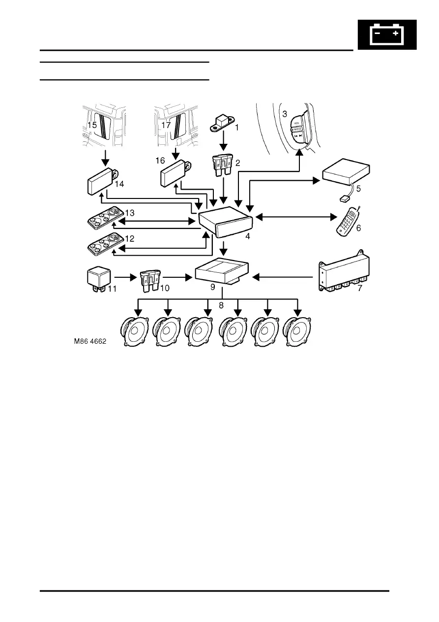
High line ICE system control diagram
1 Fusible link
2 Battery power supply fuse
3 Remote radio control switches
4 Radio cassette
5 CD-autochanger
6 Telephone system interface
7 Speed signal from SLABS ECU
8 Speakers
9 Power amplifier
10 Auxiliary power supply fuse
11 Auxiliary relay
12 Radio headphone amplifier RH rear
13 Radio headphone amplifier LH rear
14 Amplifier FM aerial
15 FM aerial
16 Amplifier AM/FM aerial
17 AM/FM aerial