
Sunroof repair/diagnostic bulletin
- Make
- Land Rover
- Model
- Discovery Technical Bulletins
- Section
- Sunroof repair/diagnostic bulletin › Sunroof repair/diagnostic bulletin
SUNROOF REPAIR/DIAGNOSTIC BULLETIN
- Model
- Discovery
- Affected vehicles
- 081991 onwards
- Date
- 1996-11-19
- Reference
- 19/11/96

Bulletin text
Sunroof Repair / Diagnostic Bulletin
MODEL
Discovery
DETAIL
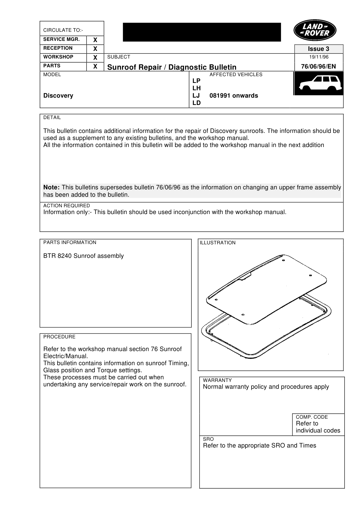
This bulletin contains additional information for the repair of Discovery sunroofs. The information should be used as a supplement to any existing bulletins, and the workshop manual. All the information contained in this bulletin will be added to the workshop manual in the next addition
Note: This bulletins supersedes bulletin 76/06/96 as the information on changing an upper frame assembly has been added to the bulletin.
ACTION REQUIRED
Information only:- This bulletin should be used inconjunction with the workshop manual.
PARTS INFORMATION
BTR 8240 Sunroof assembly
PROCEDURE
Refer to the workshop manual section 76 Sunroof Electric/Manual. This bulletin contains information on sunroof Timing, Glass position and Torque settings. These processes must be carried out when undertaking any service/repair work on the sunroof.
Issue 3 19/11/96
76/06/96/EN
AFFECTED VEHICLES
LP LH LJ 081991 onwards LD
WARRANTY
Normal warranty policy and procedures apply
COMP. CODE
Refer to individual codes
SRO
Refer to the appropriate SRO and Times
Sunroof Repair / Diagnostic Bulletin
MODEL
Discovery
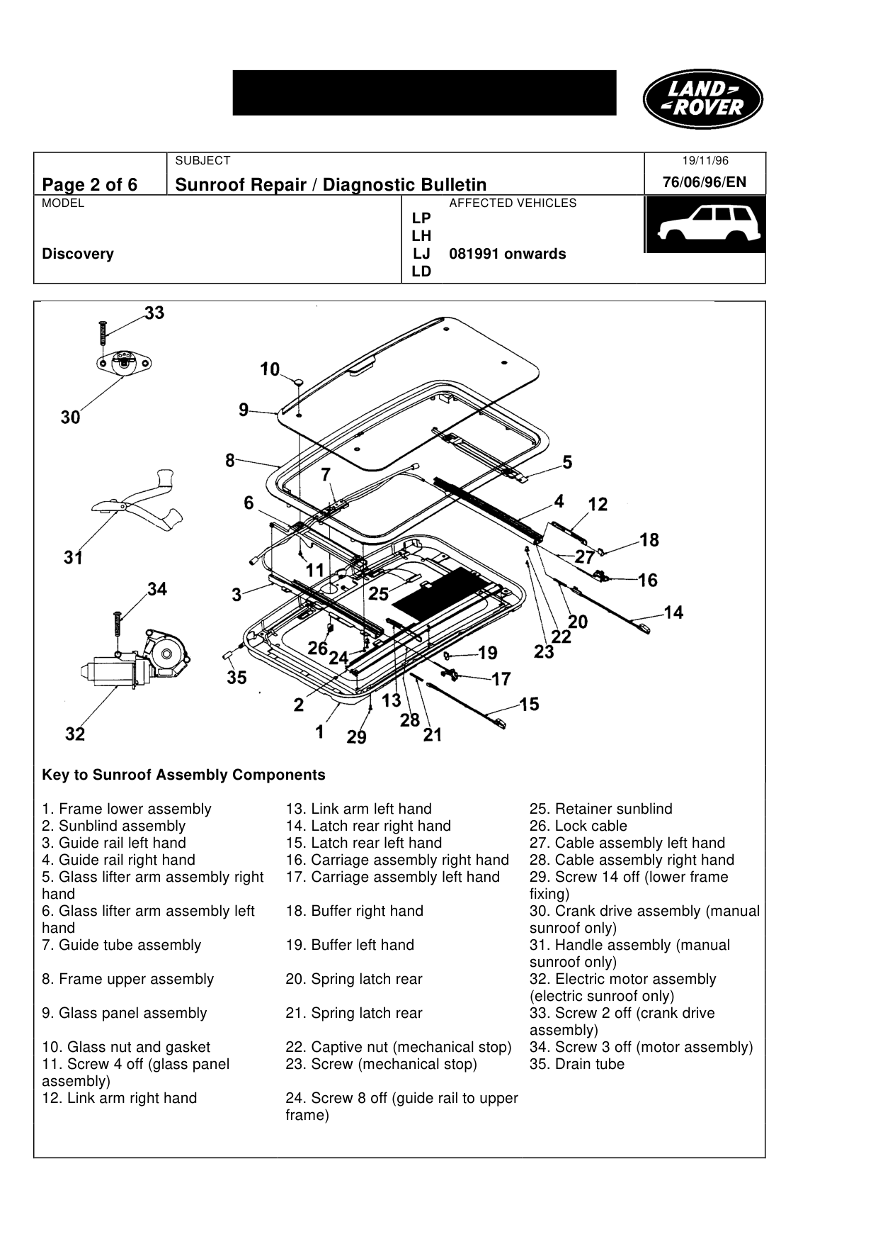
Key to Sunroof Assembly Components
1. Frame lower assembly 13. Link arm left hand 2. Sunblind assembly 14. Latch rear right hand 3. Guide rail left hand 15. Latch rear left hand 4. Guide rail right hand 16. Carriage assembly right hand 5. Glass lifter arm assembly right 17. Carriage assembly left hand hand 6. Glass lifter arm assembly left 18. Buffer right hand hand 7. Guide tube assembly 19. Buffer left hand
8. Frame upper assembly 20. Spring latch rear
9. Glass panel assembly 21. Spring latch rear
10. Glass nut and gasket 22. Captive nut (mechanical stop) 11. Screw 4 off (glass panel 23. Screw (mechanical stop) assembly) 12. Link arm right hand 24. Screw 8 off (guide rail to upper frame)
19/11/96 76/06/96/EN
AFFECTED VEHICLES
LP LH LJ 081991 onwards LD
25. Retainer sunblind 26. Lock cable 27. Cable assembly left hand 28. Cable assembly right hand 29. Screw 14 off (lower frame fixing) 30. Crank drive assembly (manual sunroof only) 31. Handle assembly (manual sunroof only) 32. Electric motor assembly (electric sunroof only) 33. Screw 2 off (crank drive assembly) 34. Screw 3 off (motor assembly) 35. Drain tube
Sunroof Repair / Diagnostic Bulletin
MODEL
Discovery
SUNROOF GLASS FRONT and REAR Refer to page 2 for key to parts information
Remove (Manual and Electric Version) 1. Open sunroof to tilt position. 2. Using a right angled screwdriver, remove 4 retaining screws and detach sunroof glass from upper frame. Retain cap nuts and washers. (if cap nuts spin during removal, tape cap nuts to glass panel).
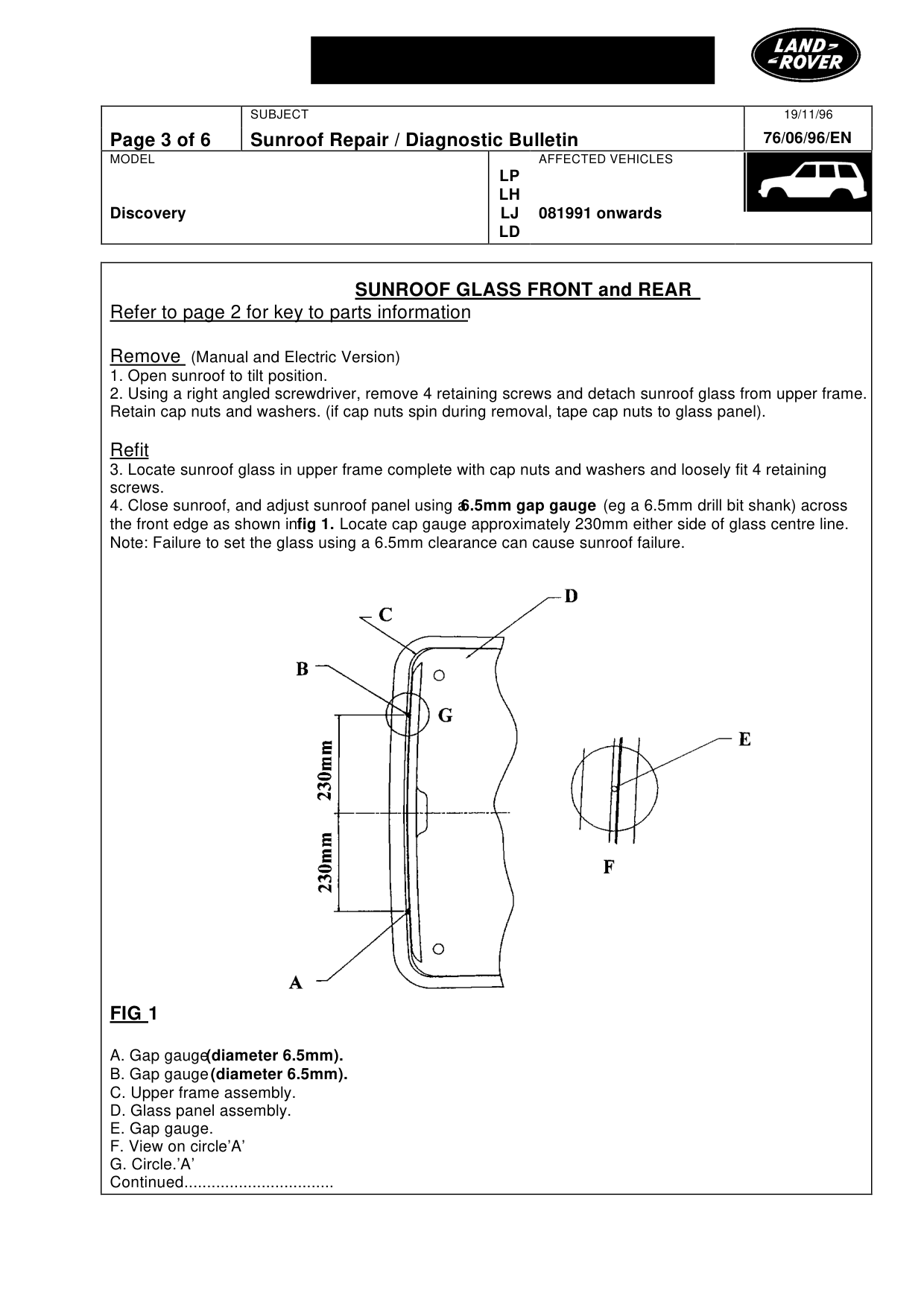
Refit 3. Locate sunroof glass in upper frame complete with cap nuts and washers and loosely fit 4 retaining screws. 4. Close sunroof, and adjust sunroof panel using a 6.5mm gap gauge (eg a 6.5mm drill bit shank) across the front edge as shown in fig 1. Locate cap gauge approximately 230mm either side of glass centre line. Note: Failure to set the glass using a 6.5mm clearance can cause sunroof failure.
FIG 1
A. Gap gauge (diameter 6.5mm). B. Gap gauge (diameter 6.5mm). C. Upper frame assembly. D. Glass panel assembly. E. Gap gauge. F. View on circle’A’ G. Circle.’A’ Continued.................................
19/11/96 76/06/96/EN
AFFECTED VEHICLES
LP LH LJ 081991 onwards LD
Sunroof Repair / Diagnostic Bulletin
MODEL
Discovery
5. Open sunroof to tilt position and tighten the 4 off retaining screws to 3.0-3.5Nm (to prevent cap nuts spinning, tape cap nuts to glass panel). 6. Operate the sunroof to close position and carry out item 4 above to ensure correct glass position has been obtained. 7. Check sunroof timing (refer to re-timing of cable mechanism procedure). 8. If timing needs adjustment, operations 4/5/6 must be repeated.
CAUTION: ENSURE WASHERS UNDER CAP NUTS DO NOT TWIST OR SPREAD OUT WHEN TIGHTENING RETAINING SCREWS. IF THIS OCCURS, CAP NUTS AND SCREWS SHOULD BE REPLACED.
TORQUE SETTING INFORMATION
Refer to page 2 for key to parts information
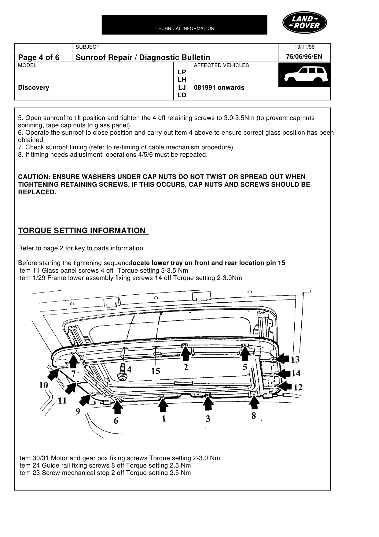
Before starting the tightening sequence locate lower tray on front and rear location pin 15 Item 11 Glass panel screws 4 off Torque setting 3-3.5 Nm Item 1/29 Frame lower assembly fixing screws 14 off Torque setting 2-3.0Nm
Item 30/31 Motor and gear box fixing screws Torque setting 2-3.0 Nm Item 24 Guide rail fixing screws 8 off Torque setting 2.5 Nm Item 23 Screw mechanical stop 2 off Torque setting 2.5 Nm
19/11/96 76/06/96/EN
AFFECTED VEHICLES
LP LH LJ 081991 onwards LD
Sunroof Repair / Diagnostic Bulletin
MODEL
Discovery
Changing an Upper Frame Assembly
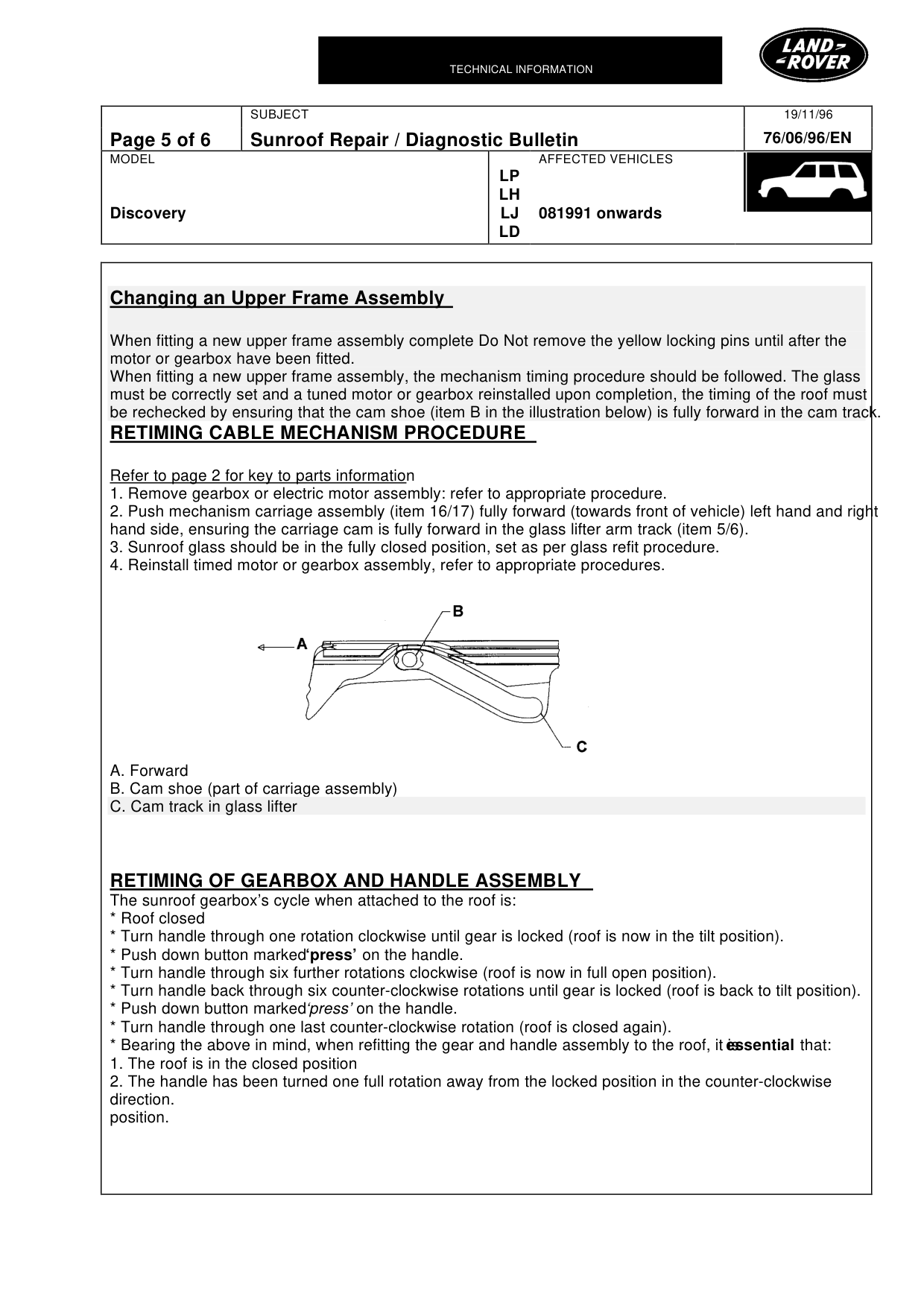
When fitting a new upper frame assembly complete Do Not remove the yellow locking pins until after the motor or gearbox have been fitted. When fitting a new upper frame assembly, the mechanism timing procedure should be followed. The glass must be correctly set and a tuned motor or gearbox reinstalled upon completion, the timing of the roof must be rechecked by ensuring that the cam shoe (item B in the illustration below) is fully forward in the cam track. RETIMING CABLE MECHANISM PROCEDURE
Refer to page 2 for key to parts information 1. Remove gearbox or electric motor assembly: refer to appropriate procedure. 2. Push mechanism carriage assembly (item 16/17) fully forward (towards front of vehicle) left hand and right hand side, ensuring the carriage cam is fully forward in the glass lifter arm track (item 5/6). 3. Sunroof glass should be in the fully closed position, set as per glass refit procedure. 4. Reinstall timed motor or gearbox assembly, refer to appropriate procedures.
A. Forward B. Cam shoe (part of carriage assembly) C. Cam track in glass lifter
RETIMING OF GEARBOX AND HANDLE ASSEMBLY The sunroof gearbox’s cycle when attached to the roof is: * Roof closed * Turn handle through one rotation clockwise until gear is locked (roof is now in the tilt position). * Push down button marked ‘press’ on the handle. * Turn handle through six further rotations clockwise (roof is now in full open position). * Turn handle back through six counter-clockwise rotations until gear is locked (roof is back to tilt position). * Push down button marked ‘press’ on the handle. * Turn handle through one last counter-clockwise rotation (roof is closed again). * Bearing the above in mind, when refitting the gear and handle assembly to the roof, it is 1. The roof is in the closed position 2. The handle has been turned one full rotation away from the locked position in the counter-clockwise direction. position.
19/11/96 76/06/96/EN
AFFECTED VEHICLES
LP LH LJ 081991 onwards LD
essential that:
Sunroof Repair / Diagnostic Bulletin
MODEL
Discovery
Frame tilt position turn counter/clockwise through one rotation, then fit to roof, which must be in closed
MOTOR SETTING
* The motor must be connected to the roof assembly, when the roof is in the closed position.
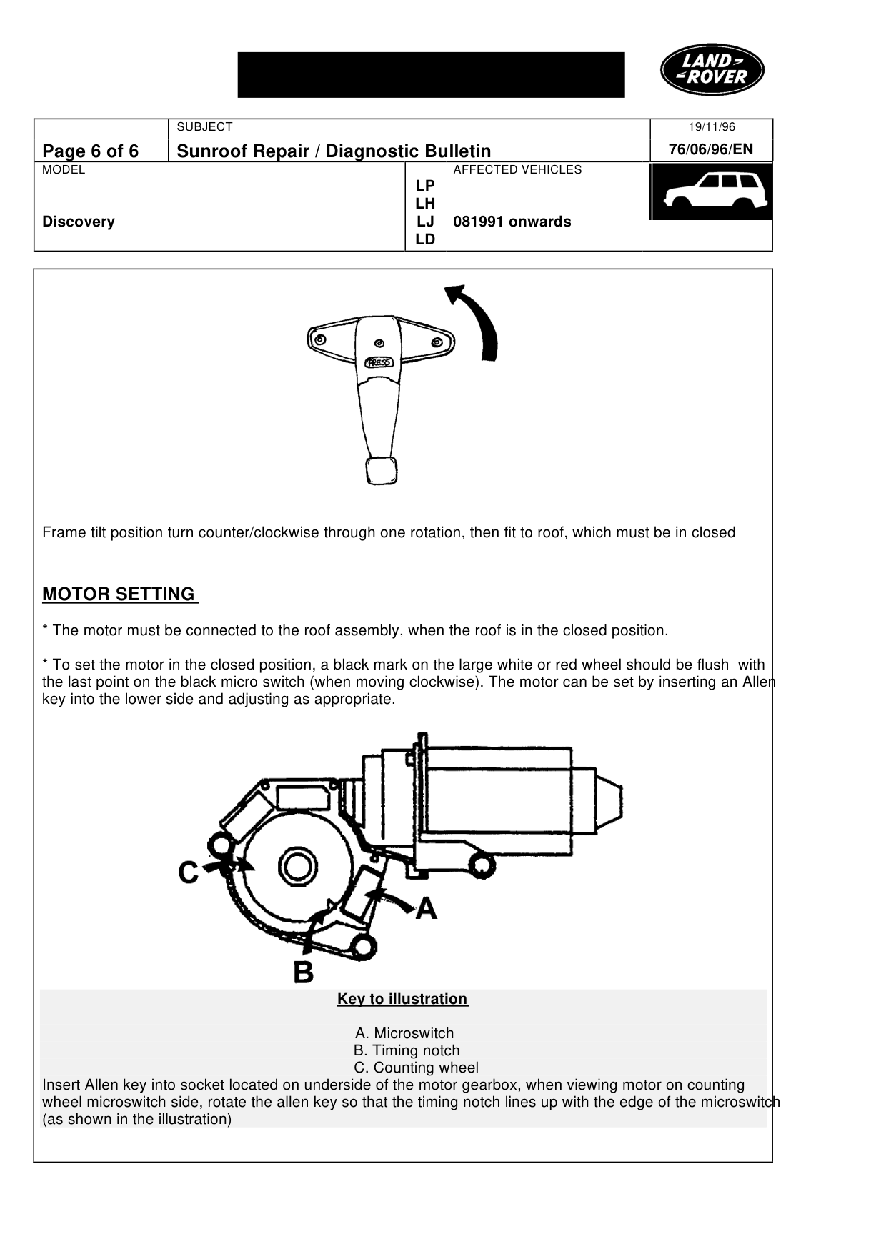
* To set the motor in the closed position, a black mark on the large white or red wheel should be flush with the last point on the black micro switch (when moving clockwise). The motor can be set by inserting an Allen key into the lower side and adjusting as appropriate.
Key to illustration
A. Microswitch B. Timing notch C. Counting wheel Insert Allen key into socket located on underside of the motor gearbox, when viewing motor on counting wheel microswitch side, rotate the allen key so that the timing notch lines up with the edge of the microswitch (as shown in the illustration)
19/11/96 76/06/96/EN
AFFECTED VEHICLES
LP LH LJ 081991 onwards LD
Parts & tools for this job For Land Rover Discovery
- TOOLOBD2 scannerSearch: OBD2 scanner
- TOOLDigital multimeterSearch: automotive digital multimeter
- TOOLBack-probe test leadsSearch: back probe test leads
Links open Amazon search results in a new tab. As an Amazon Associate I earn from qualifying purchases.