
300Tdi Discovery
SFI
15
REPAIR
REV: 09/95
Refit
25. Ensure all mating surfaces are clean.
26. Fit TP sensor. Ensure drive engages correctly
with throttle spindle.
27. Position clamp plate. Secure TP sensor with
bolts. Tighten to
2 Nm.
28. Using a new gasket, fit IAC. Secure with bolts.
Tighten to
2.3 Nm.
29. Ensure mating faces of water jacket and plenum
chamber are clean.
30. Using a new gasket, fit water jacket. Secure with
bolts. Tighten to
13 Nm.
31. Position throttle linkage bracket, fit and engage
return spring.
32. Secure linkage bracket to plenum chamber with
bolts. Tighten to
8 Nm.
33. Remove cloth from ram housing.
34. Ensure mating faces of plenum chamber and
ram pipe housing are clean.
35. Position plenum chamber. Connect coolant
hoses to water jacket. Secure with clips.
36. Remove clamp from coolant pipes. Remove
cloth.
37. Apply a thin, uniform coating of Loctite 577
sealant to sealing face of plenum chamber.
38. Fit plenum chamber.
39. Fit plenum chamber bolts. Tighten to
24 Nm.
40. Connect multiplugs to TP sensor and IAC.
41. Connect breather hose to plenum chamber.
42. Fit kick down cable to abutment bracket and fit
locknut.
43. Connect throttle cable to abutment bracket.
44. Connect vacuum hose to actuator.
45. Align throttle cable to lever. Fit clevis pin. Secure
clevis pin with split pin.
46. Align kick down cable to lever.
47. Fit clevis pin and secure clip.
48. Connect intake hose and secure with clip.
49. Reconnect battery negative lead.
50. Top up cooling system.
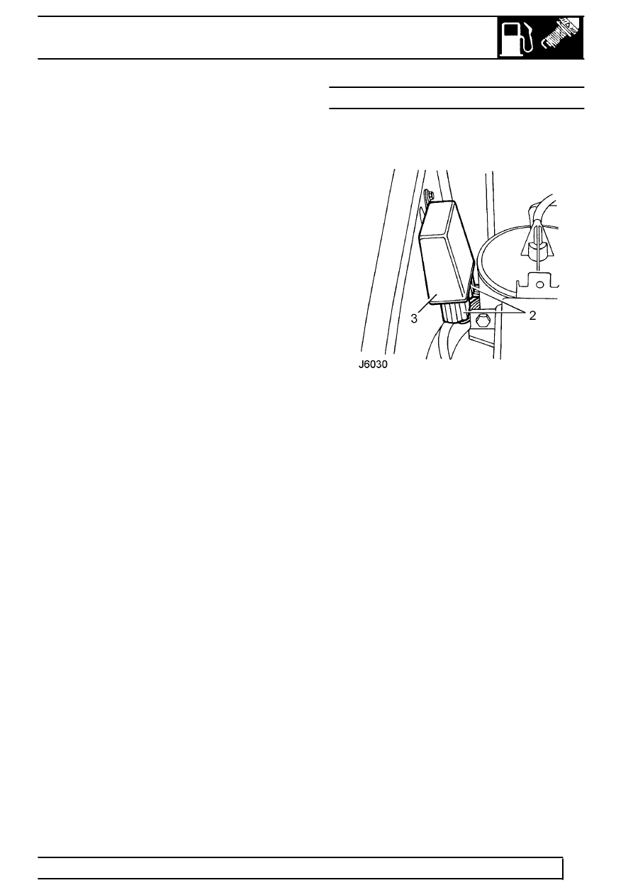
RELAY MODULE - PRE ADVANCED EVAPS
Service repair no - 18.30.71
Remove
1. Release module from bracket.
2. Disconnect 2 multiplugs.
3. Remove module.
Refit
4. Reverse removal procedure.