
Purge valve
- Make
- Land Rover
- Model
- General European On-Board Diagnostics (EOBD) Workbook
- Section
- Purge valve
For OBD vehicles with positive pressure, EVAP system leak detection capability, the atmosphere vent line from the EVAP canister connects to a port on the fuel leak detection pump via a short, large bore hose which is secured to the component ports by crimped metal clips at each end. A large bore plastic hose from the top of the leak detection pump connects to an air filter canister. Under normal operating conditions (when the fuel leak detection solenoid valve is not energised), the EVAP canister is able to take in clean air via the air filter, through the pipework and past the open solenoid valve to allow normal purge operation to take place and release any build up of EVAP system pressure to atmosphere.
Purge valve
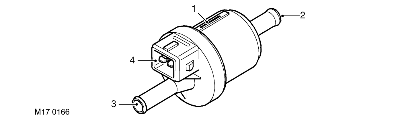
Figure 16
1.Direction of flow indicator 2.Inlet port – from EVAP canister 3.Outlet port – to inlet manifold 4.Integral electrical connector
A service port is connected in line between the EVAP canister and the inlet side of the purge valve and is rated at 1 psi maximum regulated pressure. The service port must be mounted horizontally and is located close to the bulkhead at the rear of the engine bay. The service point is used by dealers for pressure testing using specialist nitrogen test equipment for localising the source of small leaks.
The purge valve has a plastic housing, and a directional arrow is moulded onto the side of the casing to indicate the direction of flow. The head of the arrow points to the outlet side of the valve which connects to the plenum chamber.
Purge valve operation is controlled by the engine control module (ECM). The purge valve has a two-pin electrical connector which links to the ECM via the engine harness. Pin-1 of the connector is the power supply source from fuse 2 in the engine compartment fusebox, and pin-2 of the connector is the switched earth from the ECM (pulse width modulated (PWM) signal) which is used to control the purge valve operation time.
When the purge valve is earthed by the ECM, the valve opens to allow hydrocarbons stored in the EVAP canister to be purged to the engine inlet manifold for combustion.
Parts & tools for this job For Land Rover General
- PARTEngine gasket setSearch: Land Rover General engine gasket set
- TOOLTorque wrenchSearch: 3/8 inch torque wrench
- TOOLFeeler gauge setSearch: feeler gauge set
Links open Amazon search results in a new tab. As an Amazon Associate I earn from qualifying purchases.