
Freelander System Description and Operation
AIR CONDITIONING
82-2
DESCRIPTION AND OPERATION
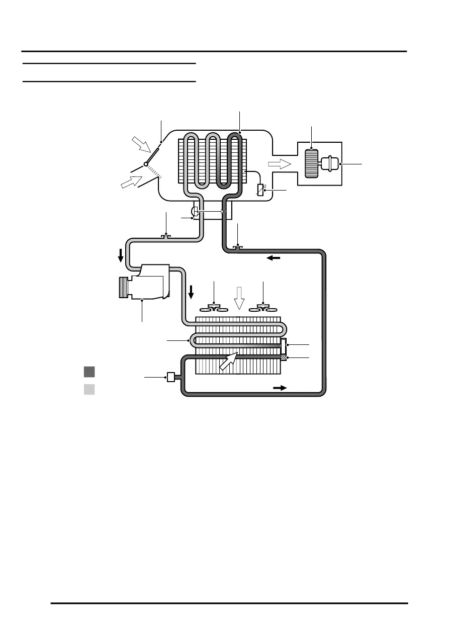
A/C System Schematic Layout
A = Refrigerant liquid; B = Refrigerant vapour
1 Cooling unit
2 Evaporator
3 Blower
4 Heater assembly
5 Evaporator temperature sensor
6 High pressure servicing connection
7 Filter (in modulator)
8 Desiccant (in modulator)
9 Cooling/condenser fan 1
10 Cooling/condenser fan 2
11 Refrigerant pressure sensor
12 Condenser
13 Compressor
14 Low pressure servicing connection
15 Thermostatic expansion valve
16 Air flows:
a Ambient air flow through condenser
b Cooling fan forced air flow through
condenser
c Recirculated air flow
d Ambient air flow through evaporator
e Cooled air flow to vehicle interior (via
heater assembly)
M82 0710
B
A
10
1
2
3
4
5
6
7
8
9
11
12
13
14
15
16a
16b
16e
16c
16d