
Freelander System Description and Operation
AIR CONDITIONING
DESCRIPTION AND OPERATION
82-1
AIR CONDITIONING
DESCRIPTION AND OPERATION
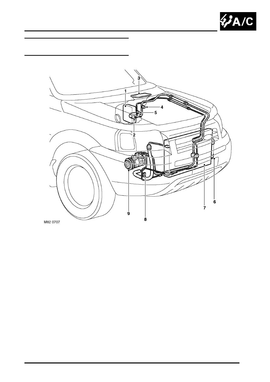
A/C Refrigerant System Component
Layout – KV6 Series Engines
RHD shown, LHD similar
1 Evaporator
2 Thermostatic expansion valve
3 Air inlet unit
4 Low pressure servicing connection
5 High pressure servicing connection
6 Modulator
7 Condenser
8 Refrigerant pressure sensor
9 Compressor