
Freelander System Description and Operation
SECURITY
DESCRIPTION AND OPERATION
86-5-1
SECURITY
DESCRIPTION AND OPERATION
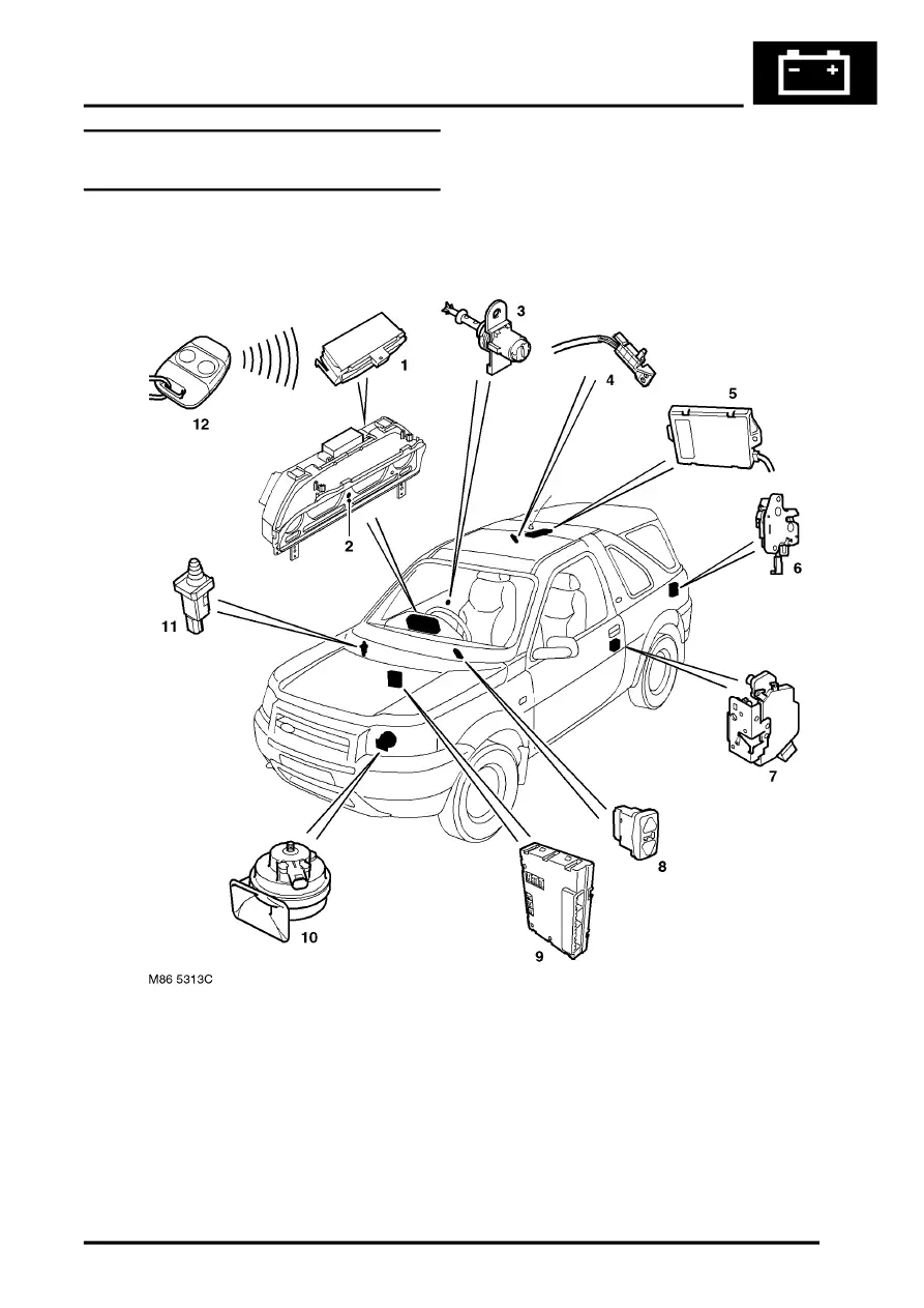
Locking and Alarm System Component
Layout
1 RF receiver
2 Alarm LED
3 Driver's door key barrel switch
4 Roof switch (3 door only)
5 Volumetric sensor
6 Tail door latch
7 Door latch
8 CDL switch
9 CCU
10 Horn
11 Bonnet switch
12 Remote handset