
Freelander System Description and Operation
SECURITY
86-5-12 DESCRIPTION AND OPERATION
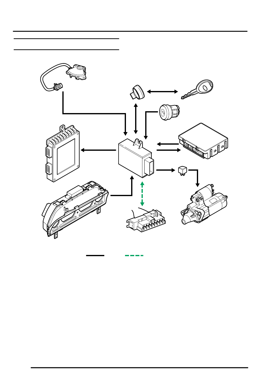
Immobilisation System Control Diagram
A = Hardwired connection; C = Diagnostic DS2 bus (EWS3–D system up to VIN 242163) or Keyword 2000* bus (from
VIN 242164)
1 Automatic transmission position switch
2 Transponder coil (ring antenna)
3 Key transponder
4 Ignition switch
5 Central control unit
6 Starter relay
7 Starter motor
8 Diagnostic socket
9 Instrument pack
10 Immobilisation ECU (up to VIN 242163 shown)
11 Engine control module
M86 5274B
A
C
10
1
7
2
3
4
11
8
9
5
6