
Freelander System Description and Operation
SECURITY
86-5-2
DESCRIPTION AND OPERATION
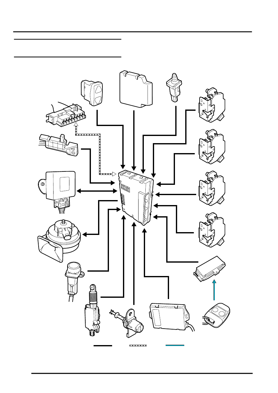
Locking and Alarm System Control
Diagram
A = Hardwired connection; F = RF transmission; J = Diagnostic ISO 9141 K line bus
M86 5314B
2
1
3
4
5
6
7
8
9
A
F
10
11
12
13
14
15
16
17
18
J