
Freelander System Description and Operation
BRAKES
DESCRIPTION AND OPERATION
70-15
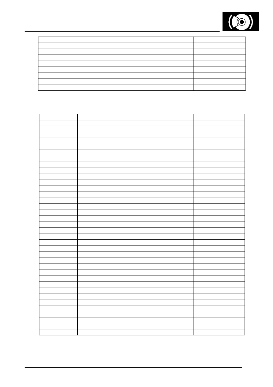
ABS ECU Connector Pin Details (From 2002 MY)
35
Not used
–
36
CAN bus 2 low (connection with ECM/EAT ECU)
Input/Output
37
CAN bus 2 high (connection with ECM/EAT ECU)
Input/Output
38 and 39
Not used
–
40
HDC relay coil
Output
41
Brake fluid level switch
Input
42
Not used
–
43
Battery power supply
Input
Pin No.
Description
Input/Output
1
Battery power supply (for return pump)
Input
2
Diagnostic ISO 9141 K line
Input/Output
3
Not used
–
4
Ignition power supply
Input
5
Not used
–
6
HDC switch
Input
7 and 8
Not used
–
9
Brake fluid level switch
Input
10
Not used
–
11
CAN bus 1 high (connection with instrument pack)
Input/Output
12
Not used
–
13
CAN bus 2 low (connection with ECM/EAT ECU)
Input/Output
14
Not used
–
15
CAN bus 1 low (connection with instrument pack)
Input/Output
16
System earth
–
17 to 23
Not used
–
24
Accelerometer earth
–
25
Not used
–
26
Accelerometer supply
Output
27 to 31
Not used
–
32
Battery power supply (for solenoid valves)
Input
33
Front RH ABS sensor earth
–
34
Front RH ABS sensor signal
Input
35
HDC relay coil
Output
36
Rear LH ABS sensor signal
Input
37
Rear LH ABS sensor earth
–
38
Brake switch (BLS contacts)
Input
39
Road speed signal
Output
40
Accelerometer signal
Input
41
Brake switch (BTS contacts)
Input
42
Rear RH ABS sensor earth
–
43
Rear RH ABS sensor signal
Input
44
CAN bus 2 high (connection with ECM/EAT ECU)
Input/Output
45
Front LH ABS sensor signal
Input
46
Front LH ABS sensor earth
–
47
System earth
–
Pin No.
Description
Input/Output