Freelander System Description and Operation

ENGINE MANAGEMENT SYSTEM - SIEMENS
18-4-14 DESCRIPTION AND OPERATION
EMS Sensors
The EMS incorporates the following sensors:
l
An APP sensor.
l
A Crankshaft Position (CKP) sensor.
l
A Camshaft Position (CMP) sensor.
l
A Mass Air Flow (MAF) sensor.
l
An Intake Air Temperature (IAT) sensor.
l
An Engine Coolant Temperature (ECT) sensor.
l
A thermostat monitoring sensor.
l
Four Heated Oxygen Sensors (HO2S).
l
Two knock sensors.
APP Sensor – Up to 2003 Model Year
The APP sensor enables the ECM to determine the throttle position requested by the driver on the accelerator pedal.
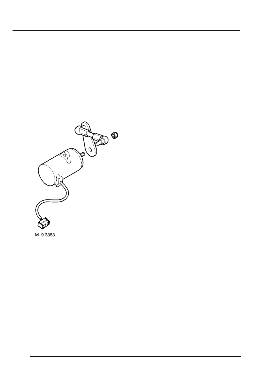
The APP sensor is installed on the pedal box and consists of a twin track potentiometer with wipers driven by a linkage
connected to the accelerator pedal. Each potentiometer track has a 5 volt supply and ground connection from the
ECM, and produces a linear signal voltage to the ECM proportional to the position of the accelerator pedal. The signal
voltage from track 1 of the potentiometer is approximately double that of the signal voltage from track 2.
From the sensor signals, the ECM determines driver demand as a percentage of pedal travel, where 0% is with the
pedal released and 100% is with the pedal fully depressed. Driver demand is then used to calculate throttle angle,
fuel quantity and ignition timing. The ECM also outputs driver demand on the CAN system, for use by the brake and
gearbox control systems.
