Freelander System Description and Operation

ENGINE MANAGEMENT SYSTEM - SIEMENS
18-4-24 DESCRIPTION AND OPERATION
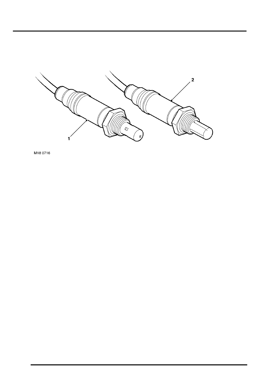
HO2S
1 Rear HO2S
2 Front HO2S
The EMS has four HO2S:
l
One upstream of each catalytic converter, identified as LH and RH front HO2S.
l
One downstream of each catalytic converter, identified as LH and RH rear HO2S.
The LH and RH front HO2S enable the ECM to determine the AFR of the mixture being burned in each cylinder bank
of the engine. The LH and RH rear HO2S enable the ECM to monitor the performance of the catalytic converters and
the front oxygen sensors, and trim fuel.
Each HO2S consists of a sensing element with a protective ceramic coating on the outer surface. The outer surface
of the sensing element is exposed to the exhaust gas, and the inner surface is exposed to ambient air. The difference
in the oxygen content of the two gases produces an electrical potential difference across the sensing element. With
a rich mixture, the low oxygen content in the exhaust gas results in a higher sensor voltage. With a lean mixture, the
high oxygen content in the exhaust gas results in a lower sensor voltage.
During closed loop control, the voltage of the two front HO2S switches from less than 0.3 volt to more than 0.5 volt.
The voltage switches between limits every two to three seconds. This switching action indicates that the ECM is
varying the AFR within the Lambda window tolerance, to maximise the efficiency of the catalytic converters.
