Freelander System Description and Operation

STEERING
57-8
DESCRIPTION AND OPERATION
The torsion bar is fitted inside the input shaft and is an interference fit in the pinion. The torsion bar is connected to
the input shaft by a drive pin, fitted after hydraulic balancing. The central diameter of the torsion bar is machined to a
smaller diameter than at each end. The smaller diameter allows the torsion bar to twist in response to torque applied
from the steering wheel in relation to the grip of the tyres on the road surface.
The pinion shaft has machined teeth on its central diameter which mate with the teeth on the steering rack. A slot
machined in the upper end of the pinion shaft mates with the dog-tooth on the input shaft. The pinion shaft locates in
a cast housing which is part of the steering rack and rotates on ball and roller bearings.
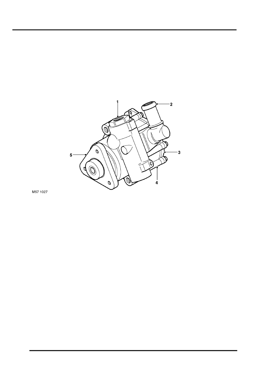
Power Assisted Steering (PAS) Pump
Td4 pump shown, K1.8 and KV6 pumps similar
1 Outlet connection
2 Inlet connection
3 Cover
4 Body
5 Drive flange
The vane type PAS pump supplies hydraulic pressure to the steering rack valve unit. The PAS pump is driven by a
Poly Vee belt from the crankshaft pulley. A self adjusting tensioner is fitted to maintain the correct belt tension.
The PAS pump comprises a body and cover which house the internal components of the pump. A pressure relief valve
assembly is installed in the body. The relief valve also incorporates a flow control valve. The pressure relief valve limits
the maximum pressure to between 120 and 127 bar (1740 and 1842 lbf/in
2
). The flow control valve limits the maximum
flow to between 5.0 and 6.0 l/min (1.32 and 1.58 US gal/min).
A shaft runs longitudinally through the pump. One end of the shaft has a drive flange which accepts the drive pulley.
The opposite end is closed by the cover. The shaft runs in bearings located in the body. Oil seals at each end of the
shaft prevent the leakage of hydraulic fluid.
