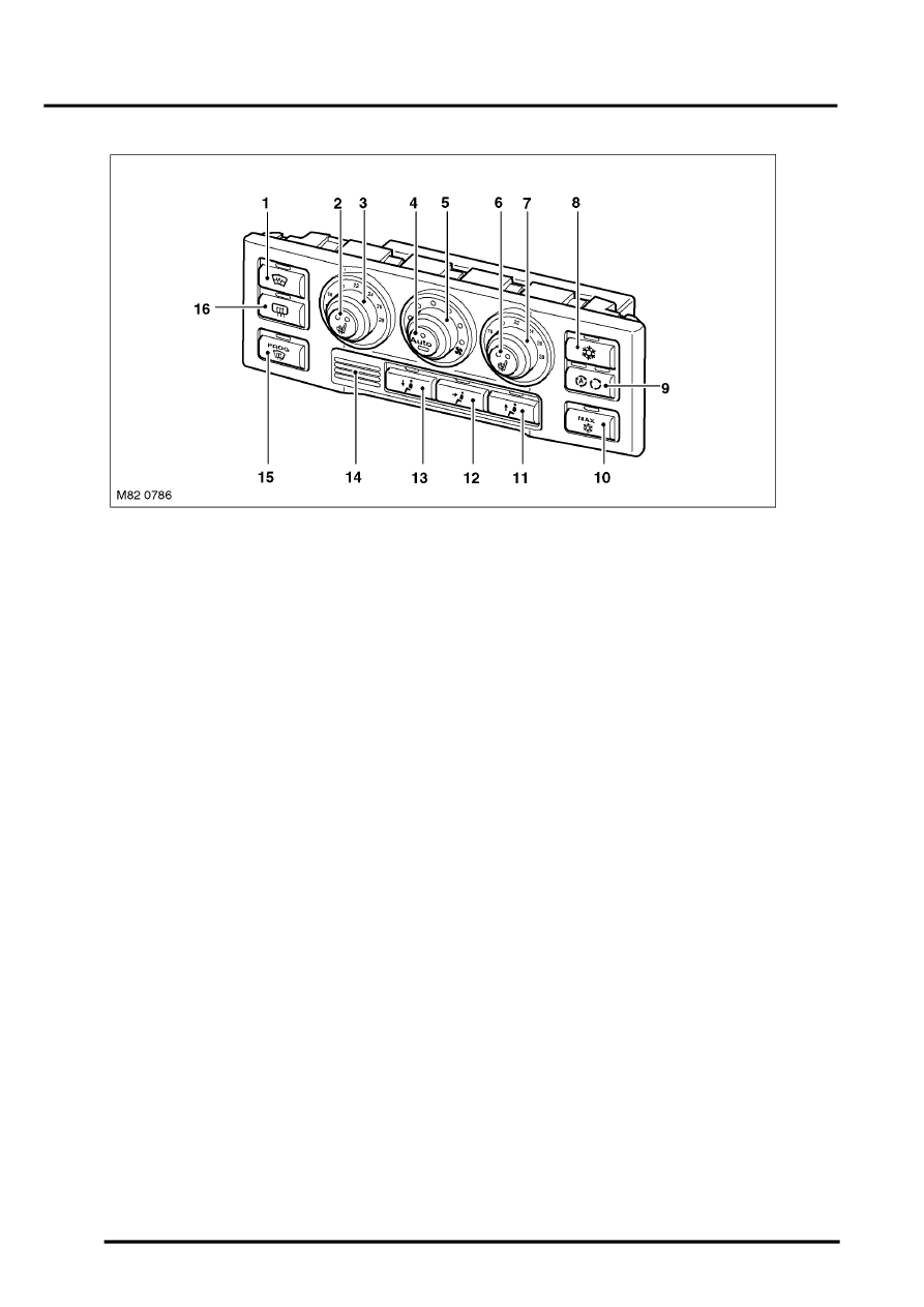
Range Rover Air Conditioning System - ATC ECU - Description & Operation

AIR CONDITIONING
82-22
DESCRIPTION AND OPERATION
High Line Control Panel
1 Windscreen heater switch
2 LH front seat heater switch
3 LH temperature switch
4 Automatic mode switch
5 Blower switch
6 RH front seat heater switch
7 RH temperature switch
8 A/C switch
9 Recirculation switch
10 Maximum A/C switch
11 Windscreen distribution switch
12 Face distribution switch
13 Footwell distribution switch
14 In-car temperature sensor
15 Defrost programme switch
16 Rear window heater switch
The switches on the high line control panel have the following functions:
l
Windscreen Heater Switch: Energises the windscreen heater and the windscreen wiper parking area heater for
a set time period, until the switch is pressed again or until the engine stops, whichever occurs first. A LED above
the switch is illuminated while the heaters are on.
l
LH and RH Seat Heater Switches: Activates the heater elements in the seat cushion and seat back at one of two
heat levels. The first press of the switch energises the heater elements at the higher heat setting and illuminates
two LED in the switch. A second press of the switch sets the heater elements to the lower heat setting and
extinguishes one of the LED's. A further press of the switch de-energises the heater elements and extinguishes
the second LED. The seat heaters remain on until selected off or the ignition is switched off.
l
LH and RH Temperature Switches: Adjusts the nominal temperature settings of the LH and RH sides of the
passenger compartment between 16 and 28
°
C (60 and 84
°
F). The temperature range is engraved on the switch
surrounds. A pointer on each switch indicates the selected temperature. In the minimum and maximum
temperature positions, the system operates at maximum cooling or maximum heating respectively.
l
Automatic Mode Switch: Activates the automatic modes for air volume and distribution and also activates the
compressor. Separate LED's in the automatic mode switch illuminate when the blower and the distribution control
flaps are in automatic mode. Manually selecting the blower speed or a distribution switch extinguishes the related
LED.
l
Blower Switch: For manual adjustment of blower speed. Up to seven LED's in the switch surround illuminate to
indicate the selected blower speed.
l
A/C Switch: Controls activation of the A/C compressor. Allows the A/C compressor to be selected off for economy
operation. A LED above the switch is illuminated when the A/C compressor is selected on.
l
Recirculation Switch: For manual or automatic selection of fresh or recirculated air. Two LED's above the switch
illuminate to indicate the mode and position of the recirculation flaps. The first press of the switch sets the
recirculation flaps to automatic mode and illuminates the LH LED. A second press of the switch manually sets
the recirculation flaps to the recirculation position, extinguishes the LH LED and illuminates the RH LED. A further
press of the switch manually sets the recirculation flaps to the fresh air position and extinguishes the RH LED.
