
L322 Range Rover System Description and Operation
AIR CONDITIONING
DESCRIPTION AND OPERATION
82-27
An ECU integrated into the FBH unit controls the operation of the FBH unit and the FBH fuel pump. The ATC ECU
controls the changeover valve. System operation is initiated by:
l
The instrument pack, via the ATC ECU, using I and K bus messages, for parked heating selections made on the
Multi Information Display (MID) or Multi-Function Display (MFD)
l
The remote handset, via the TV antenna, TV amplifier and the FBH receiver, using radio and hardwired signals,
for instant activation of parked heating
l
The ATC ECU, using K bus messages, for additional heating while the engine is running.
FBH Fuel Pump
The FBH fuel pump regulates the fuel supply to the FBH unit. The FBH fuel pump is installed below the RH side of
the fuel tank in a rubber mounting attached to the rear subframe. The pump is a self priming, solenoid operated
plunger pump. The ECU in the FBH unit outputs a pulse width modulated signal to control the operation of the pump.
When the pump is de-energised, it provides a positive shut-off of the fuel supply to the FBH unit.
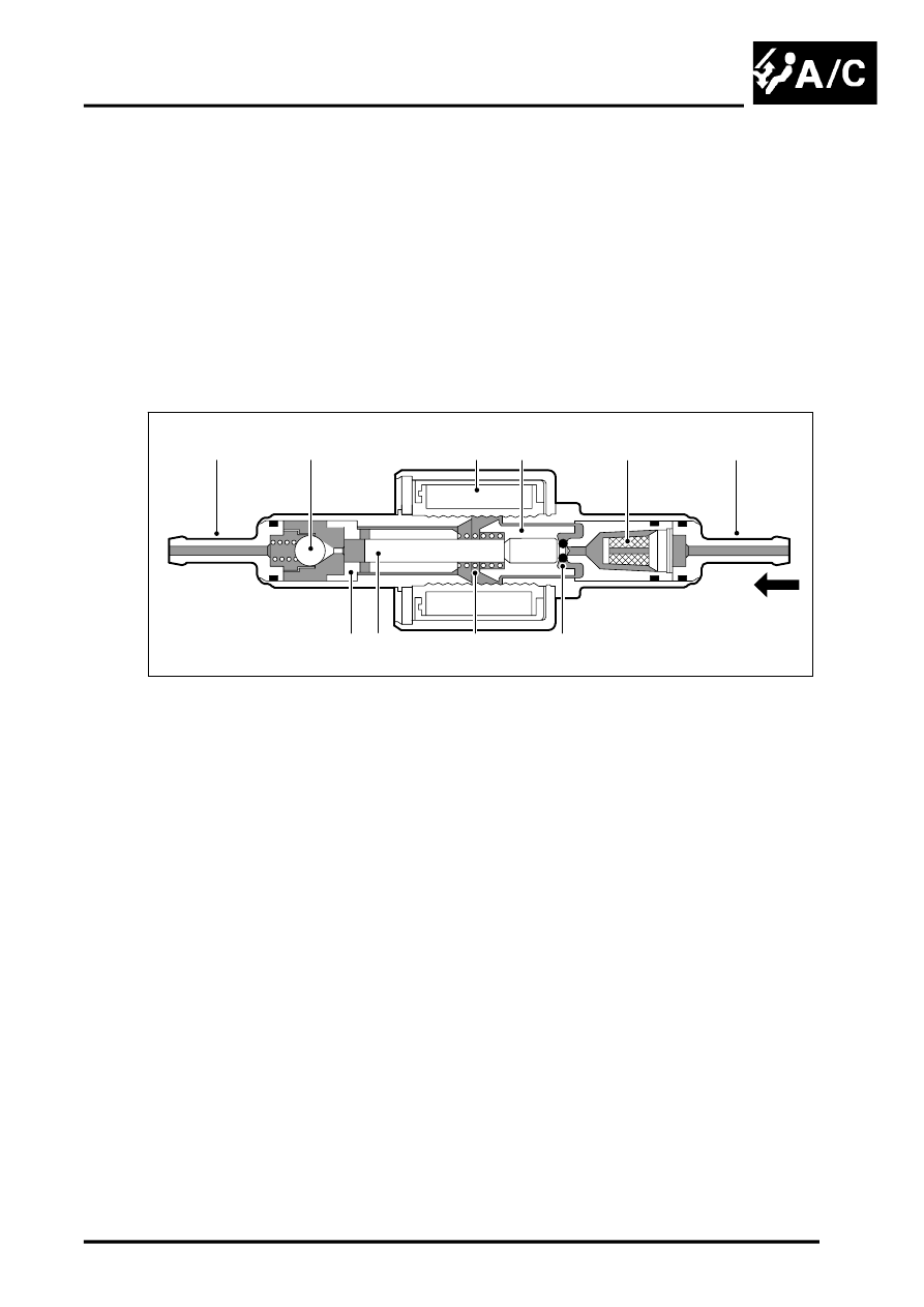
Sectioned View of FBH Fuel Pump
1 Solenoid coil
2 Plunger
3 Filter insert
4 Fuel line connector
5 'O' ring seal
6 Spring
7 Piston
8 Bush
9 Fuel line connector
10 Non return valve
The solenoid coil of the FBH fuel pump is installed around a housing which contains a plunger and piston. The piston
locates in a bush, and a spring is installed on the piston between the bush and the plunger. A filter insert and a fuel
line connector are installed in the inlet end of the housing. A non return valve and a fuel line connector are installed
in the fuel outlet end of the housing.
While the solenoid coil is de-energised, the spring holds the piston and plunger in the 'closed' position at the inlet end
of the housing. An 'O' ring seal on the plunger provides a fuel tight seal between the plunger and the filter insert,
preventing any flow through the pump. When the solenoid coil is energised, the piston and plunger move towards the
outlet end of the housing, until the plunger contacts the bush; fuel is then drawn in through the inlet connection and
filter. The initial movement of the piston also closes transverse drillings in the bush and isolates the pumping chamber
at the outlet end of the housing. Subsequent movement of the piston then forces fuel from the pumping chamber
through the non return valve and into the line to the FBH unit. When the solenoid de-energises, the spring moves the
piston and plunger back towards the closed position. As the piston and plunger move towards the closed position, fuel
flows past the plunger and through the annular gaps and transverse holes in the bush to replenish the pumping
chamber.
M80 0471
1
2
3
4
5
6
7
8
10
9