
LR3/Disco 3
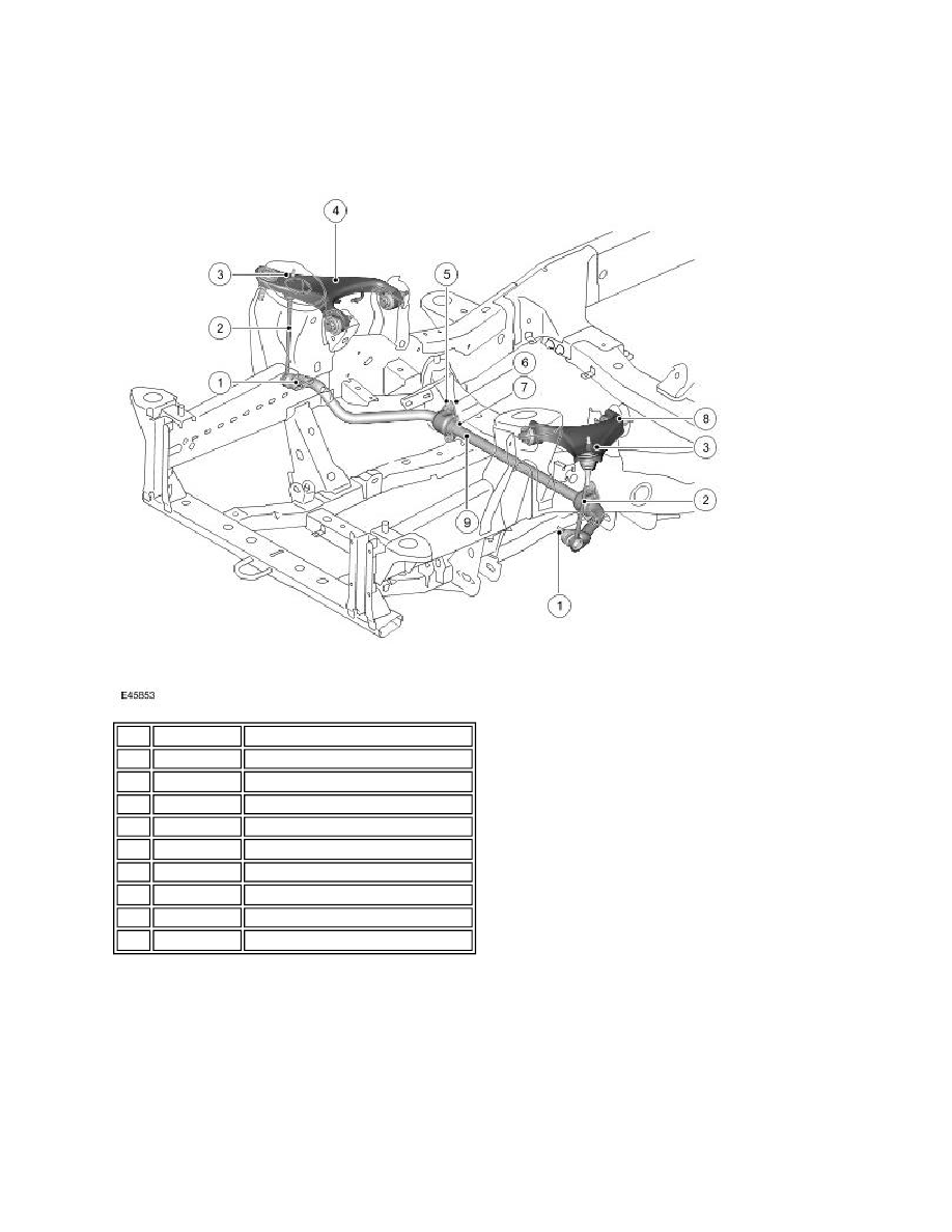
The anti-roll bar is fabricated from induction hardened, solid spring steel bar. The anti -roll bar operates, via a pair of links,
from their attachment to the upper control arm.
The anti-roll bar is attached to the forward face of the chassis front cross member. The anti -roll bar is attached to the
cross member with two, Teflon lined bushes. Brackets, which are pressed onto the bushes, are attached to the cross
member with nuts, screwed onto studs in the cross member. The anti-roll bar has crimped, 'anti-shuffle' collars pressed in
position on the inside edges of the bushes. The collars prevent sideways movement of the anti-roll bar.
The ends of the anti-roll bar are attached to the upper control arms via links. This allows the anti-roll bar to move with the
wheel travel providing maximum effectiveness. Each link has a ball joint at each end. The top ball joint is attached to the
link, parallel with the link axis. The ball joint is located in a hole in the upper control arm and secured with a self-locking
Item Part Number
Description
1
-
Nut - link to anti-roll bar (2 off)
2
-
Link (2 off)
3
-
Nut - link to upper control arm (2 off)
4
-
RH upper control arm
5
-
Nut (4 off)
6
-
Bracket (2 off)
7
-
Bush (2 off)
8
-
LH upper control arm
9
-
Anti-roll bar