
LR3/Disco 3
nut. The bottom ball joint is attached to the link at 90 degrees to the link axis. The ball joint is located in a hole in the end
of the anti-roll bar and secured with a self-locking nut. The links are not handed and therefore can be fitted to either side
of the anti-roll bar.
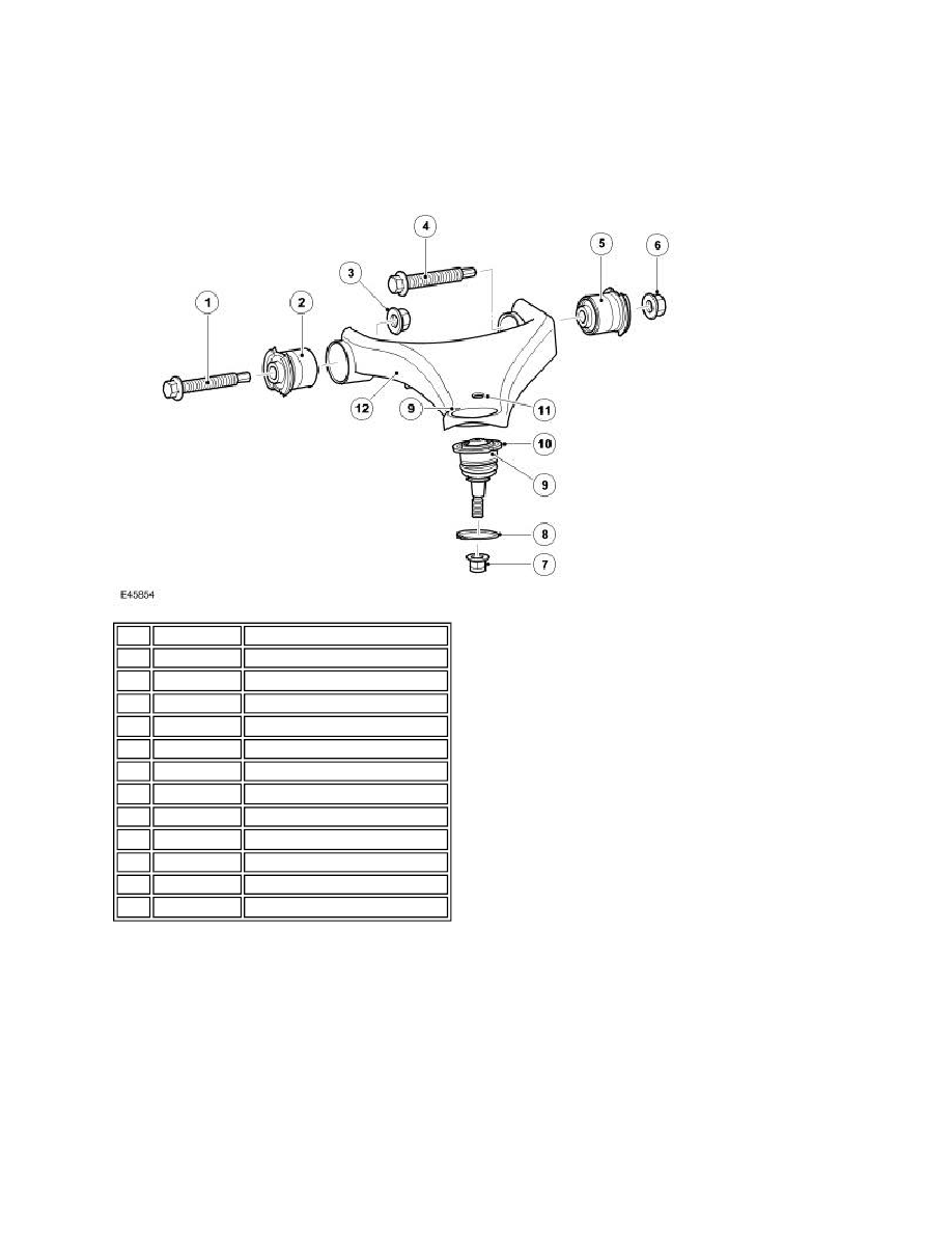
UPPER CONTROL ARM
The upper control arm assembly comprises, the control arm, two bushes and a ball joint. The upper control arm is a
pressed steel fabrication. Its outer end has a hole to accept the ball joint. A small indentation is located adjacent to the
ball joint hole and is used to obtain the correct orientation of the ball joint. A smaller hole near the ball joint provides for
the attachment of the anti-roll bar link. The underside of the upper control arm has a bracket for attachment of the height
sensor link arm and two further brackets which secure the brake hose, pad wear sensor and wheel speed sensor cables.
The inner end of the arm has two fabricated bush housings which are welded to the arm pressing. A bush is pressed into
each housing. The bushes are located between lugs on the chassis and are secured with bolts and self-locking nuts
through metal inserts in the centre of the bushes.
The ball joint in pressed into the upper control arm. The ball joint is an interference fit in the hole which prevents the ball
joint from moving. A circlip is fitted to the ball joint to retain it in the hole. The top face of the ball joint has two semi-circular
cut-outs. One of these cut-outs must be aligned with the small indentation in the upper control arm to ensure the correct
Item Part Number
Description
1
-
Flanged bolt
2
-
Bush
3
-
Self locking nut
4
-
Flanged bolt
5
-
Bush
6
-
Self locking nut
7
-
Self locking nut
8
-
Circlip
9
-
Timing marks
10
-
Ball joint
11
-
Anti-roll bar link attachment hole
12
-
Upper control arm