
LR3/Disco 3
The anti-roll bar is fabricated from heat treated, solid, spring steel bar. The anti -roll bar operates, via a pair of links, from
its attachment to the lower control arms.
The anti-roll bar is located on the upper face of a combined body mount and anti -roll bar bracket which is welded to each
chassis side member. The anti-roll bar is attached to the brackets with two, Teflon lined bushes. The bushes are fitted
with brackets, which are pressed onto the bushes and secured to the chassis brackets with bolts.
The anti-roll bar has crimped, 'anti-shuffle' collars pressed into position on the inside edges of the bushes. The collars
prevent sideways movement of the anti-roll bar.
The ends of the anti-roll bar are attached to the lower control arms via links. This allows the anti-roll bar to move with the
wheel travel providing maximum effectiveness. Each link has a ball joint at each end. The top ball joint is attached to the
link at 90 degrees to the link axis and is located in a hole in the end of the anti-roll bar and secured with a self locking nut.
The bottom ball joint is also attached to the link at 90 degrees to the axis of the link and is located a hole in a bracket on
the lower control and arm and secured with a self-locking nut. The links are not handed and therefore can be fitted to
either side of the anti-roll bar.
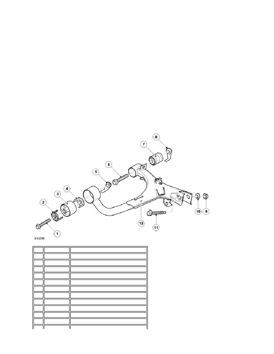
UPPER CONTROL ARM
Item Part Number
Description
1
-
Bolt
2
-
Bumpstop clip
3
-
Forward bush
4
-
Bumpstop clip
5
-
Caged nut
6
-
Bolt
7
-
Rearward bush
8
-
Caged nut
9
-
Self-locking nut - upper knuckle ball joint
10
-
Eccentric washer - upper knuckle ball joint
11
-
Cam bolt - upper knuckle ball joint