
LR3/Disco 3
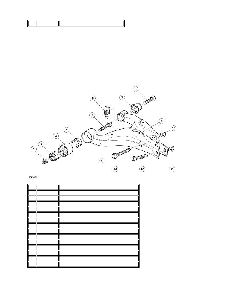
The upper control arm locates in brackets on the upper surface of each chassis side member. The upper control arm
assembly comprises the control arm and two bushes. The upper control arm is a pressed steel fabrication. Its outer end
has two brackets with slotted holes which locate the upper ball joint of the knuckle. The ball joint is secured in the upper
control arm with a cam bolt, eccentric washer and a self-locking nut. The cam bolt and the eccentric washer allow for the
adjustment of the wheel camber.
Two fabricated tubular housings provide the location for the forward and rearward bushes. The bushes, which are
pressed into the housings, locate between brackets on the chassis side members and are secured with bolts and caged
nuts through metal inserts in the centre of the bushes.
LOWER CONTROL ARM
The lower control arm locates in brackets on the lower surface of each chassis side member. The lower control arm
12
-
Upper control arm
Item Part Number
Description
1
-
Self-locking nut
2
-
Clip
3
-
Forward bush
4
-
Clip
5
-
Bolt
6
-
Nut and retainer
7
-
Rearward bush
8
-
Bolt
9
-
Anti-roll bar link bracket
10
-
Self-locking nut - damper lower attachment
11
-
Self-locking nut - knuckle upper ball joint attachment
12
-
Bolt - knuckle upper ball joint attachment
13
-
Bolt - damper lower attachment
14
-
Lower control arm