
LR3/Disco 3
assembly comprises the control arm and two bushes. The lower control arm is a pressed steel fabrication. Its outer end
has two brackets which locate the lower ball joint of the knuckle. The ball joint is secured with a bolt and self-locking nut.
The lower control arm also provides for the attachment of the damper bush which is secured with a bolt and a self-locking
nut.
A bracket, welded to the upper surface of the lower control arm, allows for the attachment of the anti-roll bar link, bottom
ball joint which is secured with a self-locking nut.
Two fabricated tubular housings provide the location for the forward and rearward bushes. The bushes, which are
pressed into the housings, locate between brackets on the chassis side members. The forward bush is secured to the
chassis bracket with a bolt and self-locking nut. The rearward bush is secured to the chassis bracket with a bolt and a nut
and retainer. The nut and retainer allows for easy installation or removal of the bolt by removing the requirement to hold
the self-locking nut when installing or removing the bolt.
On vehicles fitted with coil springs there is a jacking bracket located on the lower control arm.
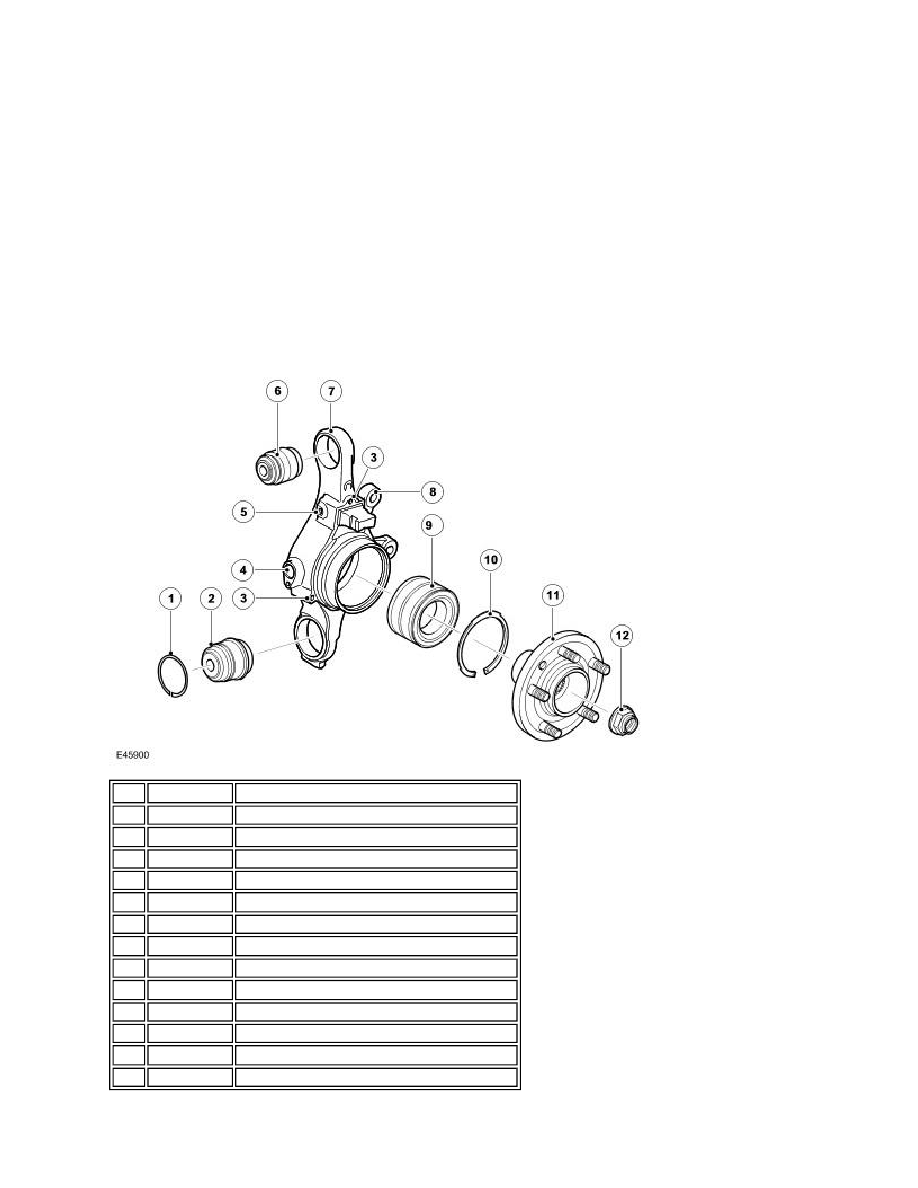
WHEEL KNUCKLE, WHEEL HUB AND BEARING ASSEMBLY
Item Part Number
Description
1
-
Circlip - lower ball joint
2
-
Ball joint - lower
3
-
Park brake assembly attachment holes
4
-
Wheel speed sensor location
5
-
Wheel speed sensor cable bracket attachment
6
-
Ball joint - upper
7
-
Knuckle
8
-
Brake caliper attachment holes
9
-
Wheel bearing
10
-
Circlip - wheel bearing retention
11
-
Nut - halfshaft
12
-
Wheel hub
13
-
Wheel studs