
LR3/Disco 3
Connector C2447
Controller Area Network (CAN) Signals
The TPMS module sends and receives a number of digital messages via the medium speed CAN. The received
messages are used for the operation of the TPMS. The transmitted messages comprise of TPMS status and requests to
the instrument cluster to illuminate warnings indicators and/or display messages in the message center.
Received Messages
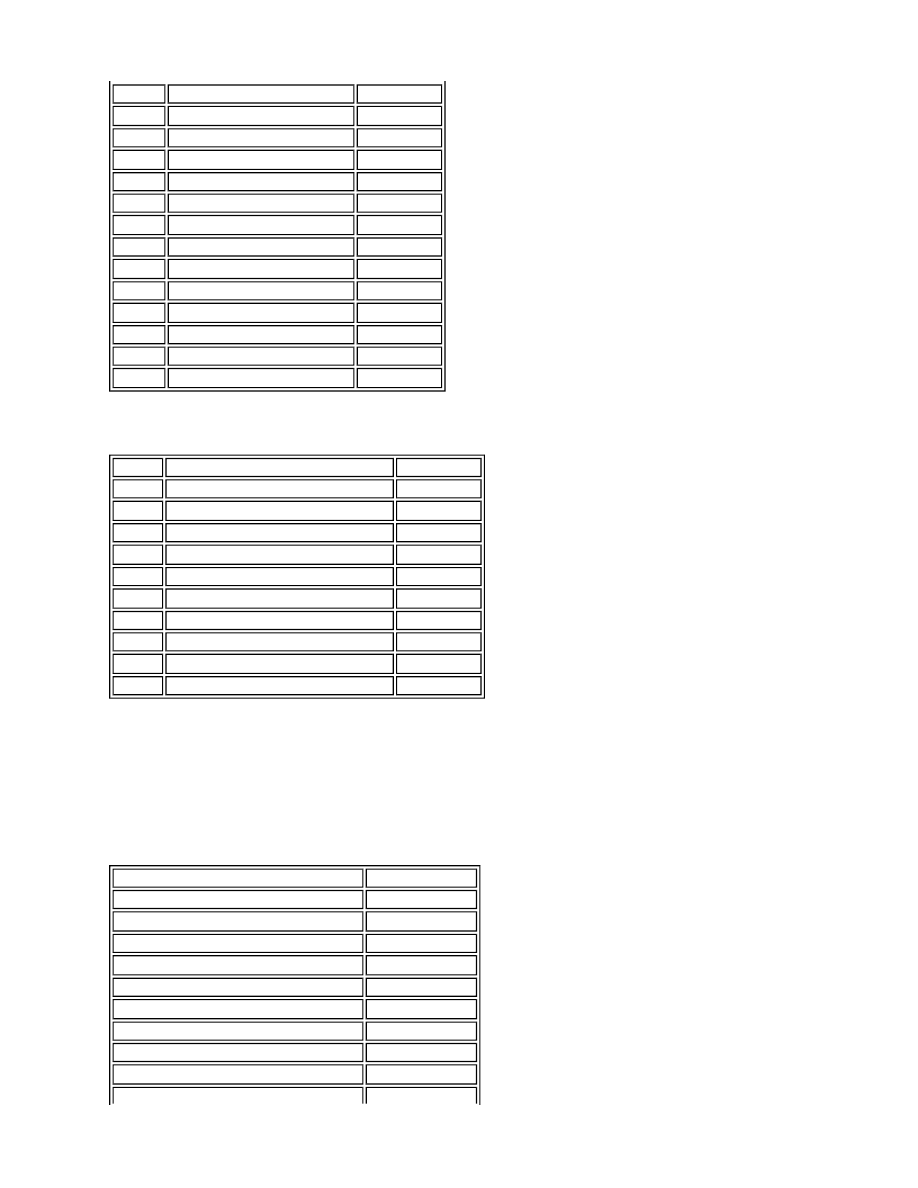
The TPMS module receives the messages shown in the following table.
1
Not used
-
2
CAN LOW - IN
Input/Output
3
CAN HIGH - IN
Input/Output
4
Not used
-
5
TPMS Switch LED Drive
Output
6
Not used
-
7
TPMS Switch
Input
8
Ignition 12V supply
Input
9
Not used
-
10
CAN LOW - OUT
Input/Output
11
CAN HIGH - OUT
Input/Output
12
Ground
Input
13 to 15
Not used
-
16
12V Permanent battery supply
Input
Pin No.
Description
Input/Output
1 to 4
Not used
-
5
Rear LH initiator - Signal positive (+)
Output
6
Rear LH initiator - Signal negative (-)
Output
7
Rear RH initiator - Signal positive (+)
Output
8
Rear RH initiator - Signal negative (-)
Output
9 to 12
Not used
-
13
Front LH initiator - Signal positive (+)
Output
14
Front LH initiator - Signal negative (-)
Output
15
Front RH initiator - Signal positive (+)
Output
16
Front RH initiator - Signal negative (-)
Output
Message
Transmitted By
Vehicle speed
ABS module
External ambient temperature - corrected
ATC module
Side lamp status
CJB
Ignition switch status
CJB
Odometer value
Instrument cluster
Minute counter
Instrument cluster
Vehicle voltage level
Instrument cluster
Engine crank relay status
ECM
Diagnostic physical request
T4