
LR3/Disco 3
Transmitted Messages
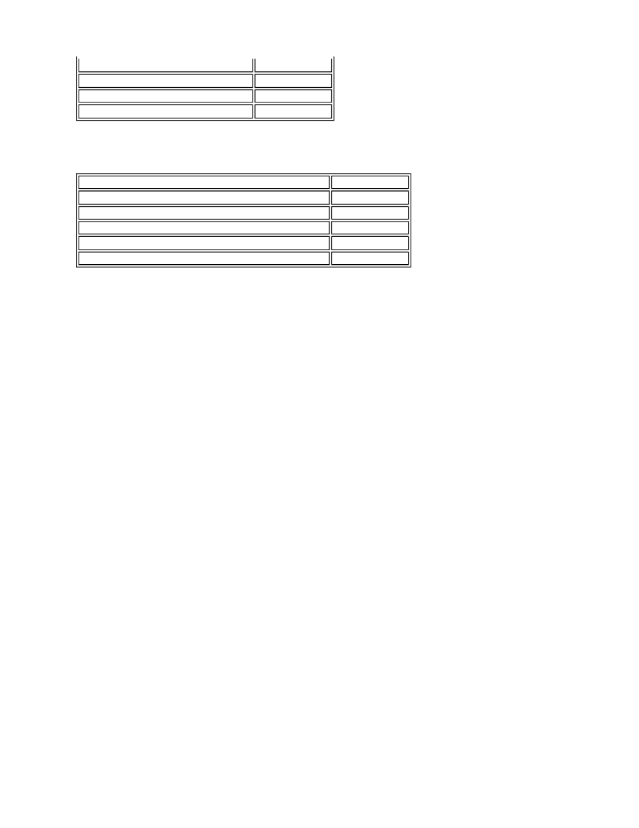
The TPMS module transmits the messages shown in the following table.
Diagnostics
The TPMS module has a diagnostic connection via the medium speed CAN to enable system status and faults to be
retrieved using T4.
Additionally, an on-board diagnostic routine within the TPMS module constantly monitors the system and alerts the driver
to a system faults by illuminating the amber or red warning indicators, emitting a tone from the instrument cluster sounder
and/or displaying a message in the instrument cluster message center.
Fault Detection
If a sensor fails, the amber warning indicator in the instrument cluster will be illuminated. On vehicles with a high line
instrument cluster, a message 'Tire Pressure Monitoring Sensor Fault' will be displayed in the message center in addition
to the amber warning indicator.
If more than one sensor fails or the TPMS module develops a fault, the amber warning indicator will be illuminated. On
vehicles with a high line instrument cluster, a message 'Tire Pressure Monitoring System Fault' will be displayed in the
message center in addition to the amber warning indicator. This fault could also be caused if RF interference near the
vehicle affects the system signal reception. When the interference has ceased, the fault will be automatically cancelled
and the TPMS will operate normally.
If a tire pressure sensor battery voltage becomes low, the sensor transmits a message to the TPMS module. The module
stores the low battery condition as a fault flag in its memory with no other visual warnings displayed. If the battery fails,
the sensor will stop transmitting and the TPMS module will display a 'Front left tyre not being' monitored message, for
example in the message center on high line instrument clusters or the red warning indicator will be illuminated on low line
instrument clusters. The dealer should interrogate the TPMS module using T4 for the fault flag to determine the cause of
the message. If the battery has failed the sensor must be replaced and the stored fault flags removed using T4. The
TPMS module will learn the identification of the new sensor when the vehicle is driven. If the replaced sensor is fitted to
the spare wheel (if fitted), its identification must be manually programmed into the module using T4.
CONTROL DIAGRAM
NOTE:
Diagnostic functional request
T4
Engine running status
ECM
Master car configuration identification
Instrument cluster
Car configuration parameters
Instrument cluster
Message
Received By
TPMS diagnostic response
T4
TPMS Red warning indicator request at 35% tire deflation
Instrument cluster
TPMS yellow warning indicator request at 25% tire deflation Instrument cluster
TPMS audible alert
Instrument cluster
TPMS message display request
Instrument cluster
A = Hardwired; F = RF Transmission; N = Medium Speed CAN Bus