
LR3/Disco 3
the ECU memory. Once set, the calibration is not required to be performed unless the air suspension control module is
removed or replaced, a height sensor is removed or replaced or a suspension arm to which the sensor is connected is
removed or replaced. If the removed height sensor is subsequently refitted, the calibration procedure will have to be
performed to ensure the integrity of the system.
If the air supply unit, the reservoir, a valve block, a damper module or the air harness is removed or replaced, the system
will not require recalibration.
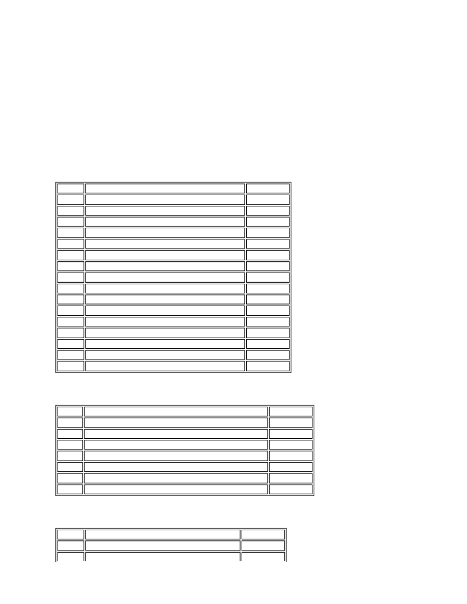
Inputs and Outputs
The air suspension control module uses four harness connectors for all inputs and outputs.
The following tables show the details of the signals or electrical supplies on each connector pin.
Connector C2030
Connector C2320
Connector C2321
Pin No.
Description
Input/Output
1
Rear control valve - Cross link valve - positive (+)
Output
2
Not used
-
3
Not used
-
4
Not used
-
5
Air supply unit - Motor temperature sensor signal
Input
6
Not used
-
7
Air supply unit - Motor temperature sensor - Ground
Input
8
Switch pack display - Raising LED
Output
9
Switch pack display - Lowering LED
Output
10
Switch pack display - On-road mode LED
Output
11
Rear control valve - Cross link valve - negative (-)
Input
12 to 16
Not used
-
17
Switch pack display - Crawl mode LED
Output
18
Switch pack display - Access mode LED
Output
19
Not used
-
20
Switch pack - Raise switch signal
Input
Pin No.
Description
Input/Output
1
Air supply unit voltage signal input from Air supply unit relay
Input
2
Reservoir control valve - Pressure sensor - 5 Volt supply
Output
3
Reservoir control valve - Pressure sensor - Signal
Input
4
Reservoir control valve - Pressure sensor - Ground
Input
5
Air supply unit - Exhaust valve - Negative (-)
Input
6
Air supply unit - Exhaust valve - Positive (+)
Output
7 and 8
Not used
-
Pin No.
Description
Input/Output
1
12V Permanent battery supply
Input