
LR3/Disco 3
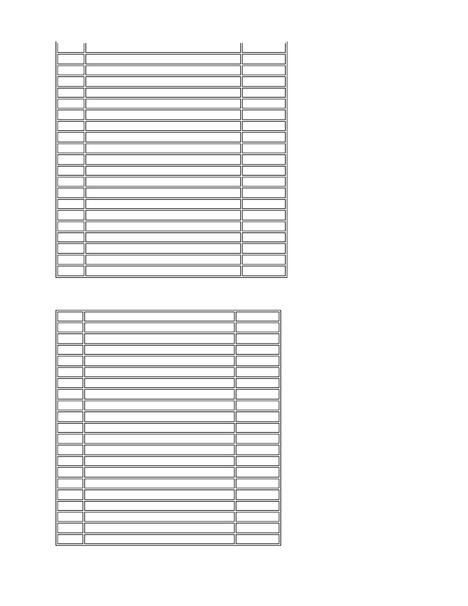
Connector C0867
The air suspension control module uses inputs received on the CAN bus from other vehicle systems. The system uses
2
Compressor temperature sensor - Signal
Input
3
Front LH height sensor - 5 Volt supply
Output
4
Front LH height sensor - Signal
Input
5
Front LH height sensor - Ground
Input
6
Air supply unit relay coil - positive
Output
7
Air supply unit relay coil - ground
Input
8
Reservoir control valve coil - positive (+)
Output
9
Front control valve - RH corner valve - negative (-)
Input
10
Front control valve - RH corner valve - positive (+)
Output
11
Front control valve - LH corner valve - negative (-)
Input
12
Front control valve - LH corner valve - positive (+)
Output
13
Not used
-
14
Front RH height sensor - 5V supply
Output
15
Front RH height sensor - signal
Input
16
Front RH height sensor - ground
Input
17
Compressor temperature sensor - ground
Input
18 to 20
Not used
-
21
Reservoir control valve coil - negative (-)
Input
22
Front control valve - cross link valve - positive (+)
Output
23
Front control valve - cross link valve - negative (-)
Input
24
Ground
Input
Pin No.
Description
Input/Output
1
Rear control valve - LH corner valve positive (+)
Output
2
Rear control valve - LH corner valve negative (-)
Input
3
Door status signal from CJB
Input
4
Switch pack - Lower switch signal
Input
5
Rear LH height sensor - 5 Volt supply
Output
6
Rear LH height sensor - Signal
Input
7
Rear LH height sensor - Ground
Input
8
Rear RH height sensor - 5 Volt supply
Output
9
Rear RH height sensor - Signal
Input
10
Rear RH height sensor - Ground
Input
11
Rear control valve - RH corner valve positive (+)
Output
12
Rear control valve - RH corner valve negative (-)
Input
13
Air suspension control - CJB signal
Input
14
Switch pack display - LED ground
Input
15
Switch pack display - LED high
Output
16
CAN IN positive (+)
Input
17
CAN OUT positive (+)
Output
18
CAN OUT negative (-)
Input
19
CAN IN negative (-)
Output
20
12 Volt ignition switch supply
Input