
LR3/Disco 3
The driver can also ignore the system's warnings signals and allow the height to change automatically. For example,
increasing the vehicle speed to more than 25 mph (40 km/h) will cause the control module to automatically change the
ride height from off-road mode to on-road mode.
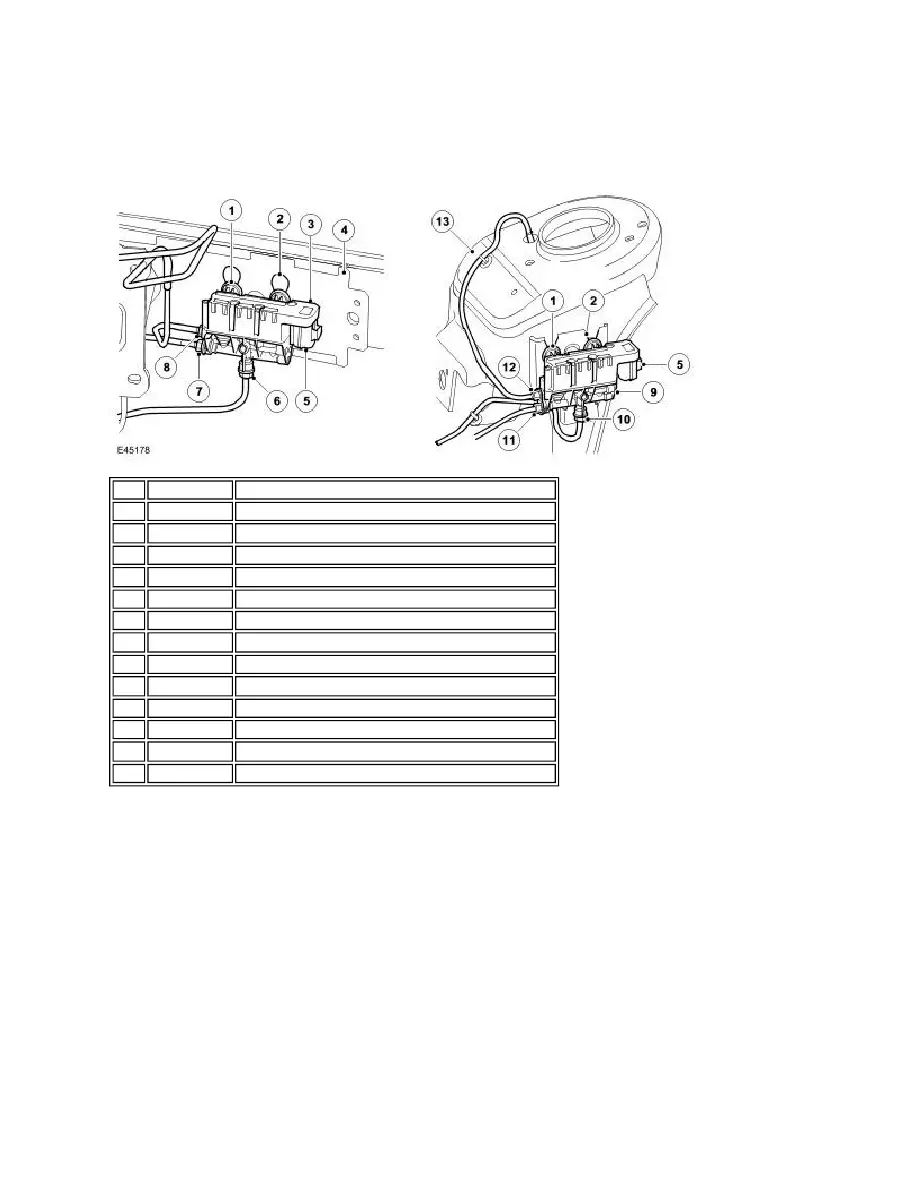
FRONT AND REAR AXLE VALVE BLOCKS
The front and rear axle valve blocks are similar in their design and construction and control the air supply and distribution
to the front or rear pairs of air spring damper modules respectively. The difference between the two valves is the
connections from the valve block to the left and right hand air spring damper modules and the valve size. It is important
that the correct valve block is fitted to the correct axle. Fitting the incorrect valve block will not stop the air suspension
system from functioning but will result in slow raise and lower times and uneven raising and lowering between the front
and rear axles.
The front valve block is attached to the right hand end of the front bumper armature assembly. The valve block has three
attachment lugs which are fitted with isolation rubber mounts. The rubber mounts locate in slots in the armature. The
valve lugs locate in the holes above the slots and are pulled downwards into positive location in the slots.
The rear valve block is located on the forward face of the left hand rear suspension turret. The valve block has three
attachment lugs which are fitted with isolation rubber mounts which locate in a bracket with three slotted holes. The
bracket is attached to the left hand side of the chassis. The isolation rubber mounts locate in the 'V' shaped slots and are
pulled downwards into positive location in the slots.
The front and rear valve blocks each have three air pipe connections which use 'Voss' type air fittings. One connection is
an air pressure inlet/outlet from the reservoir valve block. The remaining two connections provide the pressure
connections to the left and right hand air springs.
Item Part Number
Description
1
-
Isolation rubber mounts (3 off)
2
-
Location slots
3
-
Front valve block, valves and solenoid assembly
4
-
Front bumper armature
5
-
Electrical connector
6
-
LH air spring damper module air harness connection
7
-
Air inlet/outlet connection
8
-
RH air spring damper module air harness connection
9
-
Rear valve block, valves and solenoid assembly
10
-
RH air spring damper module air harness connection
11
-
Air inlet/outlet connection
12
-
LH air spring damper module air harness connection
13
-
Rear suspension turret