
LR3/Disco 3
Each valve block contains three solenoid operated valves; two corner valves and one cross-link valve. Each of the valve
solenoids is individually controlled by the air suspension control module. The solenoids have a resistance value of 2
Ohms at a temperature of 20°C (68°F).
Corner Valves
The corner valves control the flow of air into and out of the individual air springs. When the solenoid is de -energised, the
corner valves are held in a closed position by internal springs. When the solenoid is energised, the valve armature moves
and allows air to flow into or out of the air spring.
Cross Link Valves
The cross-link valve provides a connection between the two air springs on the same axle. When de-energised, the cross-
link valve prevents air passing from one air spring to another. When the solenoid is energised, the valve spool moves and
allows air to pass from one air spring to the other. This increases wheel articulation and improves ride comfort at low
vehicle speeds.
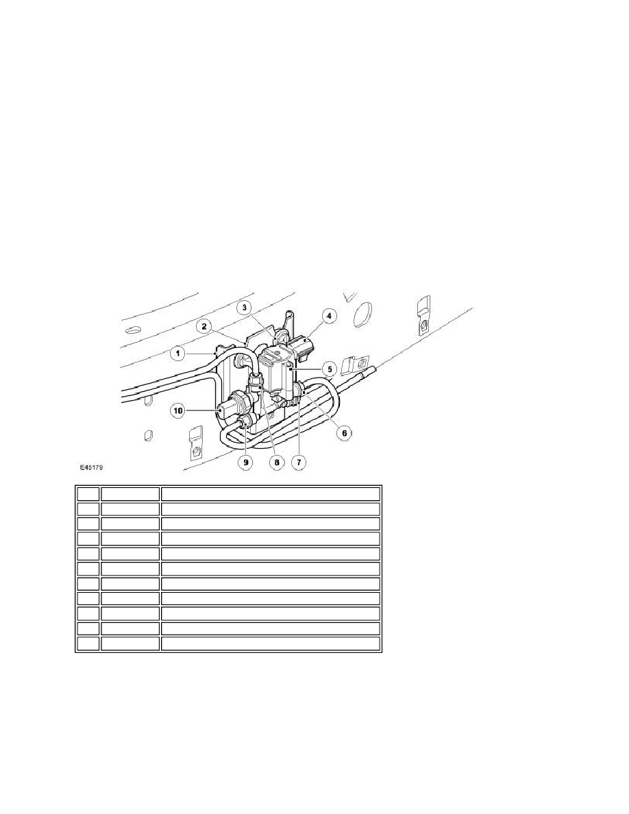
RESERVOIR VALVE BLOCK
The reservoir valve block controls the storage and distribution of air from the reservoir. The reservoir valve block also
contains the system pressure sensor.
The reservoir valve block is attached to a bracket on the outside of the left hand chassis rail, between the reservoir and
the air supply unit. The valve block is located within the air supply unit acoustic box to protect it from dirt ingress and
damage from stones. The valve block has three attachment lugs which are fitted with isolation rubber mounts which locate
in the chassis bracket which has three slotted holes. The isolation rubber mounts locate in the 'V' shaped slots and are
pulled downwards into positive location in the slots.
Item Part Number
Description
1
-
Chassis mounting bracket
2
-
Location slot
3
-
Isolation rubber mounts (3 off)
4
-
Electrical connector
5
-
Reservoir valve block, valves and solenoid assembly
6
-
Reservoir connection
7
-
Rear valve block connection
8
-
Front valve block connection
9
-
Air supply unit connection
10
-
Pressure sensor