
LR3/Disco 3
The control module is connected on the Controller Area Network (CAN) bus and controls the differential operation using
CAN messages from other control modules on the network.
The control module uses three connectors for all inputs and outputs. It receives a permanent power supply via a 40A
fusible link located in the Battery Junction Box (BJB), and an ignition supply via fuse 24 located in the Central Junction
Box (CJB).
The control module memorises the position of the electronic rear differential motor when the ignition is switched off.
The control module controls the closed loop position sensing system within the motor and regulates the power supply to
the motor.
If the control module is replaced, T4 must be connected to the vehicle and the electronic rear differential control module
self-calibration procedure must be performed. This procedure must also be performed if the motor or differential assembly
is replaced.
If a fault occurs with the electronic rear differential, the control module or one of the required input signals, i.e. road speed
signal, the control module records an error code and a warning lamp, in the instrument cluster, illuminates permanently.
Electronic Rear Differential Control Module Pin Out Details
Connector C2162
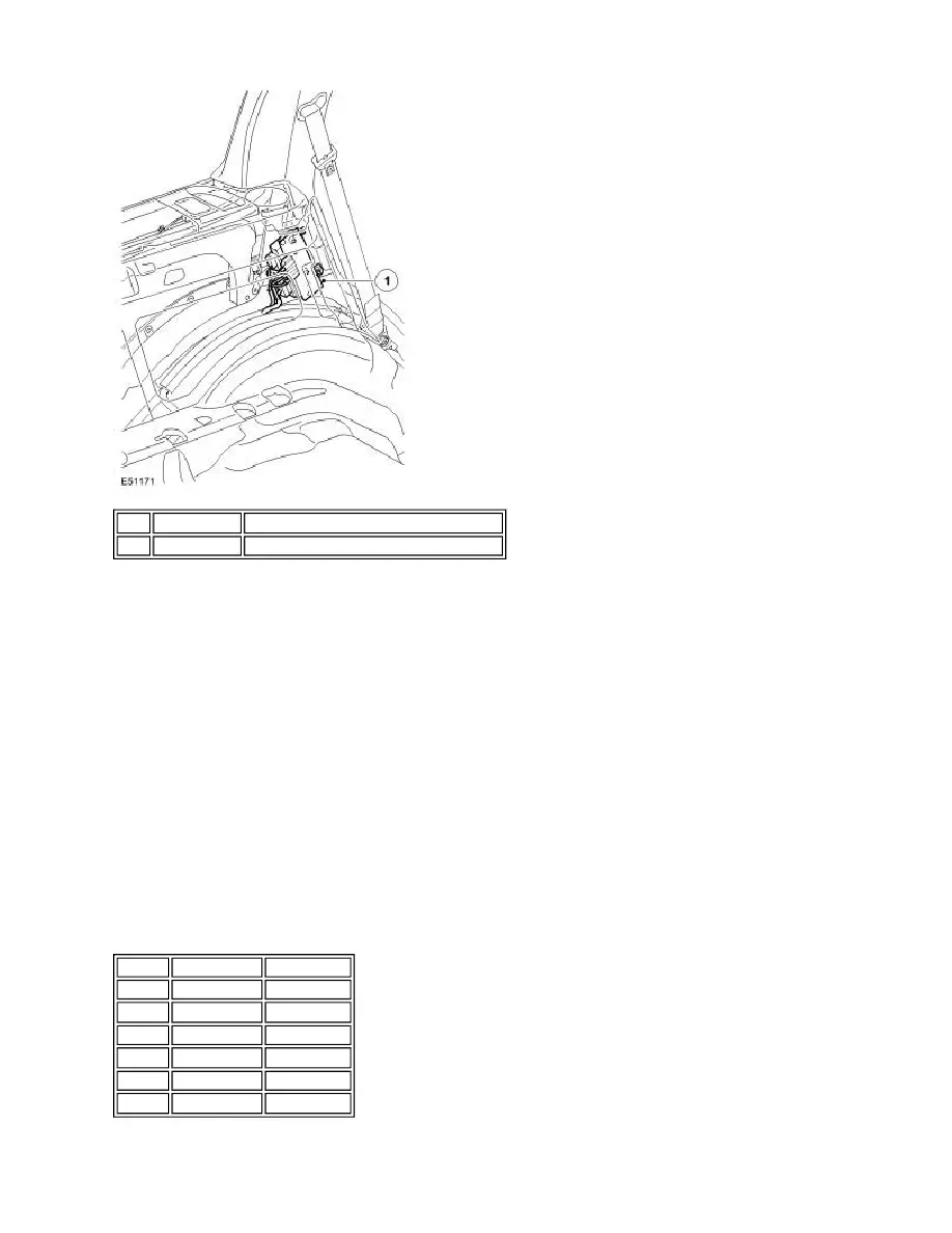
Item Part Number
Description
1
-
Electronic rear differential control module
Pin No. Description Input/output
1
Not used
-
2
CAN bus low
Input/output
3
CAN bus high Input/output
4
Not used
-
5
CAN bus high Input/output
6
CAN bus low
Input/output