
LR3/Disco 3
l
Halfshaft seals
l
Needle roller bearing assembly
l
Chassis bush/fixings
l
Actuator motor
l
Temperature sensor
l
Control module and bracket
l
Lubricant.
DIAGNOSTICS
The electronic rear differential control module can store fault codes, which can be retrieved using T4 or a diagnostic tool
using ISO-14229 protocol.
The information is communicated via a diagnostic socket.
The diagnostic socket allows the exchange of information between the various control modules on the bus systems and
T4 or another suitable diagnostic tool. The information is communicated to the socket via the CAN bus. This allows the
retrieval of diagnostic information and programming of certain functions using T4 or another suitable diagnostic tool.
The electronic rear differential control module uses Diagnostic Trouble Codes (DTC), which relate to electronic rear
differential electrical faults.
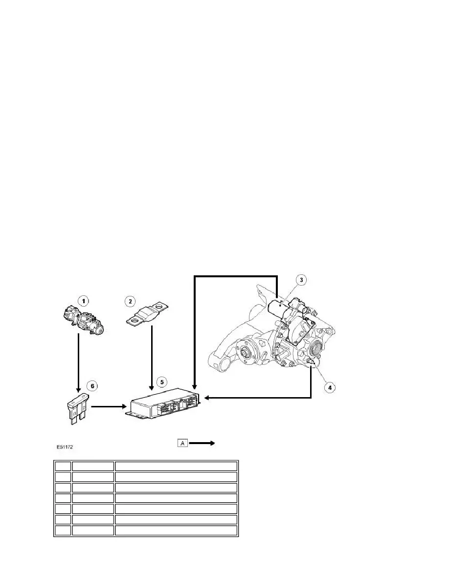
ELECTRONIC REAR DIFFERENTIAL CONTROL DIAGRAM
NOTE:
A = Hardwired
Item Part Number
Description
1
-
Ignition switch
2
-
Fusible link (battery)
3
-
Actuator motor
4
-
Oil temperature sensor
5
-
Electronic rear differential control module
6
-
Fuse (ignition)