
LR3/Disco 3
Halfshaft Joint
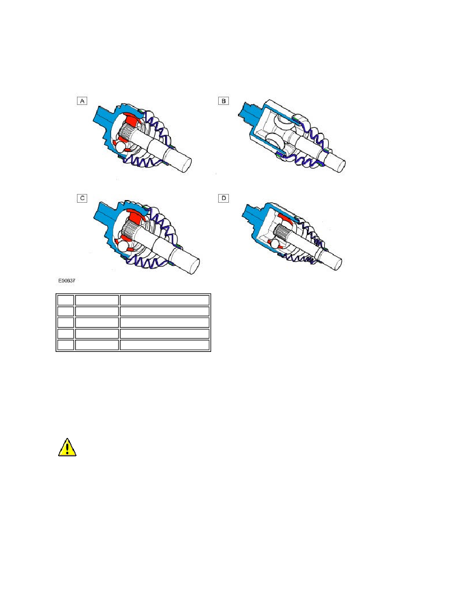
Front Drive HalfShaft – Sectional Views
The outboard and rear inboard CV joints are of the Birfield design. This design uses longitudinal, elliptical grooves, which
retain six steel balls. The balls are further retained by a cage. The constant velocity is achieved by the position of the steel
balls. If a centre line is drawn through the balls and the driven hub or differential shaft, the two centre lines always bisect
each other at the angle of drive. This condition allows the rotational speed of the driven shaft to be passed to the driven
hub or differential shaft with no loss of rotational speed regardless of the shaft angle. The CV joints are packed with
grease, which is retained in the joint by a synthetic rubber gaiter. The gaiter is retained at each end by a metal clamp,
which provides a water tight seal to prevent the ingress of dirt and moisture. The CV joints are retained on their respective
shaft or tube by an internal snap ring. The snap rings are located in a groove on each shaft or tube end and locate in a
mating groove in the CV joint.
The shaft is a sliding fit inside the outer tube, which allows for the small length changes, which occur with articulation of
the suspension. The shaft is located in a ball cage, which is retained inside the outer tube. The ball cage ensures that the
shaft is held rigidly in the outer tube whilst allowing it to freely move in and out of the tube as necessary. A sealing plug is
pressed into the outer tube and retains grease around the balls in the cage.
The inner CV joints are similar in design and operation to the outer joints except that the inner joints use rollers rather
than balls to transmit the drive.
Item Part Number
Description
A
-
Front outboard halfshaft joint
B
-
Rear outboard halfshaft joint
C
-
Rear inboard halfshaft joint
D
-
Front inboard halfshaft joint
CAUTION: The inner hub is not retained in the joint body on this type of joint. The joint is held together
in it's unfitted state only by the boot. Pulling on the barshaft can therefore pull the hub out of the joint body. For
this reason care must be taken when handling and fitting the front driveshafts.