
LR3/Disco 3
Inputs and Outputs
A 32 pin electrical connector on the RH side of the parking brake module provides the interface between the PCB and the
vehicle wiring.
The parking brake module is powered by two permanent battery power feeds from the Battery Junction Box (BJB). Two
connections with the Central Junction Box (CJB) provide battery voltage signals when the key is in the ignition switch (key
in) and when the ignition switch is in position II (ignition). Other hardwired inputs consist of those from the parking brake
switch and, on manual transmission models, the clutch pedal position sensor.
In addition to the hardwired connections, the parking brake module is connected to the high speed CAN bus to enable
communication with other vehicle systems.
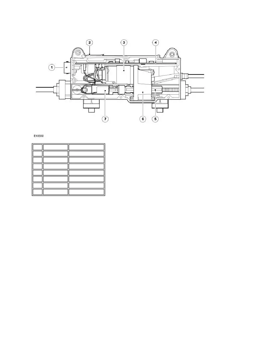
Parking Brake Module Harness Connector C2178
Item Part Number
Description
1
Electrical connector
2
Housing
3
Electric motor
4
PCB
5
Spline shaft
6
Gearbox
7
Force sensor