
LR3/Disco 3
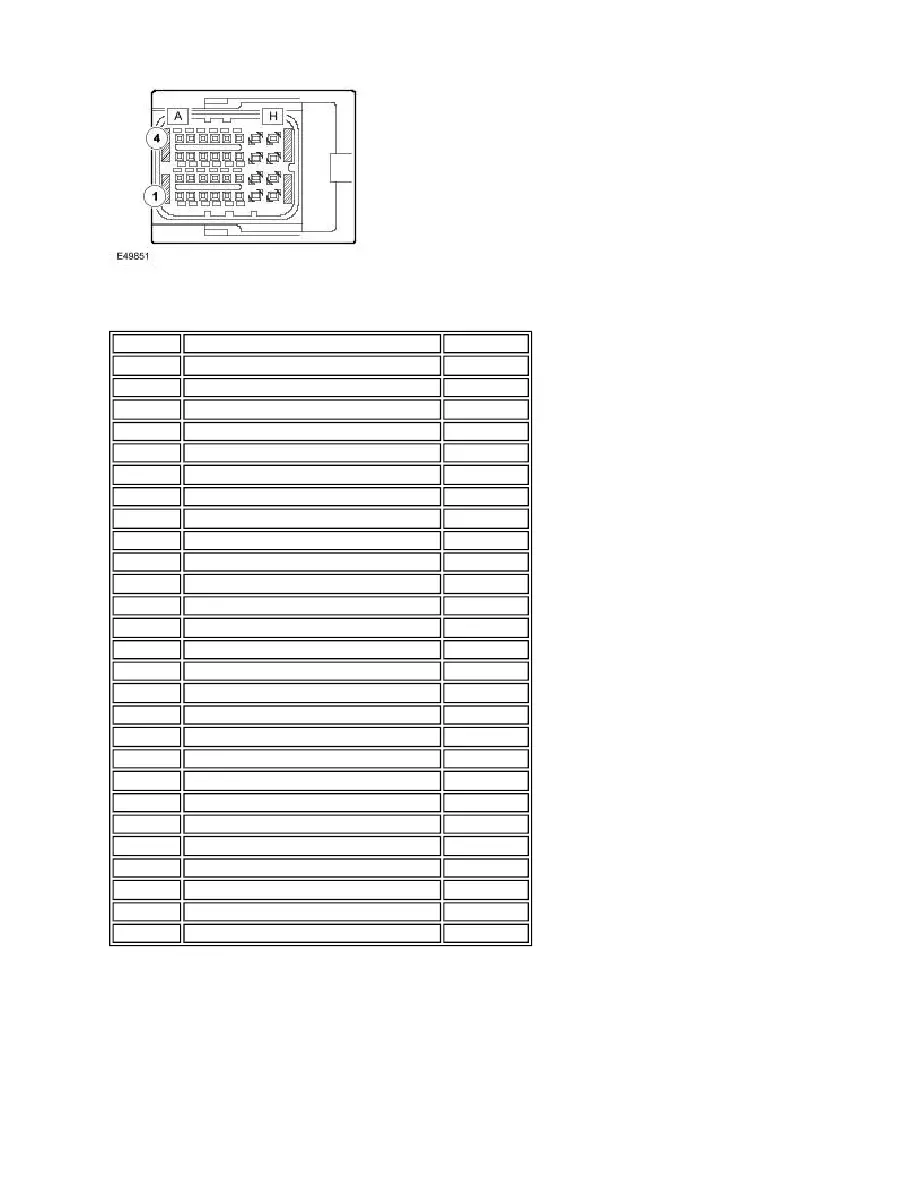
Parking Brake Module Harness Connector C2178 Pin Details
PARKING BRAKE OPERATION
The parking brake can be applied at any time provided sufficient battery power is available. For the parking brake to be
released, various pre-conditions are required. The parking brake has manual and automatic operating modes, to cater for
different operating circumstances, as detailed in the following table:
Operating Modes
Pin No.
Description
Input/Output
A1
Not used
-
A2
High speed CAN bus low out
Input/Output
A3
High speed CAN bus high in
Input/Output
A4
High speed CAN bus low in
Input/Output
B1
Not used
-
B2
High speed CAN bus high out
Input/Output
B3
Parking brake switch SW1
Input
B4
Parking brake switch SW4
Input
C1 and C2
Not used
-
C3
Parking brake switch SW2
Input
C4
Parking brake switch SW5
Output
D1 to E1
Not used
-
E2
Clutch pedal position sensor ground
Input
E3
Clutch pedal position sensor signal
Input
E4
Clutch pedal position sensor power supply
Output
F1
Not used
-
F2
Key in ignition switch
Input
F3
Ignition power supply
Input
F4
Red parking brake indicator
Output
G1
Not used
-
G2
Ground
Output
G3
Not used
-
G4
Battery power supply
Input
H1
Not used
-
H2
Ground
Output
H3
Not used
-
H4
Battery power supply
Input