
LR3/Disco 3
The filler neck of the reservoir is sealed with a cap incorporating the level switch. The level switch is operated by a
magnet, which is installed in the float on the bottom of the switch. The switch reacts to the influence of the magnetic field
surrounding the magnet.
When the reservoir is full, the float rests against the bottom of the switch and holds the level switch open. When the fluid
level decreases, the float moves down and the switch closes to connect a ground to the instrument cluster. When the
ground is made, the instrument cluster illuminates the red Light Emitting Diode (LED) in the brake warning indicator.
Vehicles with the high line instrument cluster also display an appropriate warning in the message center. For additional
information, refer to
Instrument Cluster
(413-01 Instrument Cluster)
At the beginning of each ignition cycle, the instrument cluster performs a bulb check on the brake warning indicator; the
indicator is illuminated amber for 1.5 seconds, then red for 1.5 seconds.
The instrument cluster broadcasts the status of the brake fluid level, on the high speed Controller Area Network (CAN)
bus, to the Anti-lock Brake System (ABS) module. For additional information, refer to
Anti-Lock Control - Traction
Control
(206-09A Anti-Lock Control - Traction Control)
BRAKE PIPES AND HOSES
The brake pipes and hoses connect the master cylinder to the wheel brakes via the hydraulic control unit. The pipes are
arranged to provide a front and rear split braking system. The brakes on the front axle are operated by the primary
system; the brakes on the rear axle are operated by the secondary system.
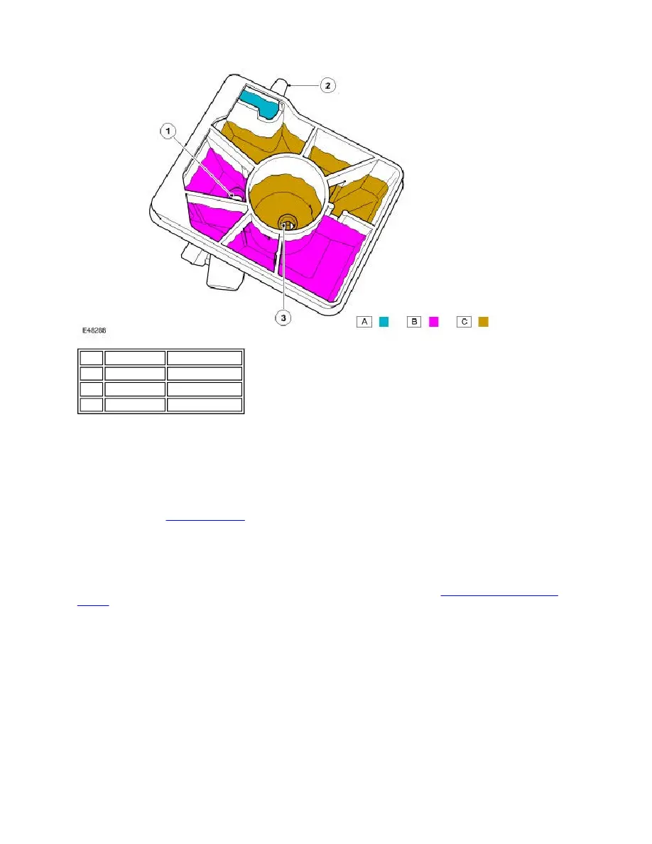
Item Part Number
Description
1
-
Primary outlet
2
-
Clutch outlet
3
-
Secondary outlet