
LR3/Disco 3
The steering gear is located at the front of the engine, below the accessory belt drive. The gear is attached to two
brackets on the chassis and is secured to the brackets with flanged bolts and caged nuts. The cage prevents the nuts
from turning when the bolts are loosened or tightened. The cage nuts can only be used once and must be replaced when
the gear is removed. For service, M12 Nylock nuts are available as a replacement for the cage nut.
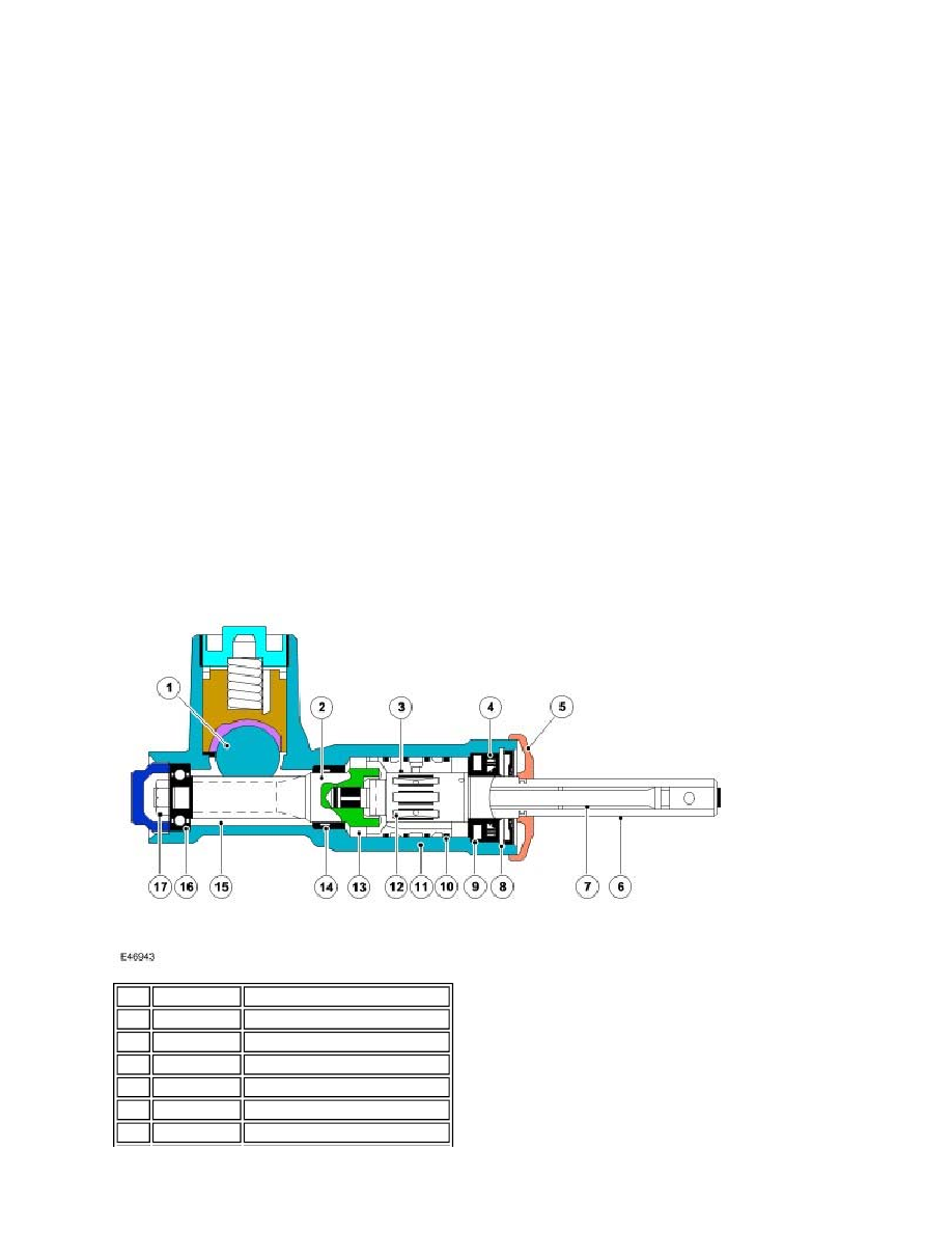
The steering gear comprises an aluminium, cast, one piece housing which contains a mechanical steering rack, a valve
unit and an integrated hydraulic power unit.
The steering gear uses a rack with an integrated piston which is guided on plain bearings within the rack housing. The
pinion, which is attached to the valve unit, runs in bearings and meshes with the rack teeth. The rack is pressed against
the pinion by a spring loaded yoke which ensures that the teeth mesh with the minimum of play. The pinion is connected
to the valve unit via a torsion bar. The rotary motion of the steering wheel is converted into linear movement of the rack by
the pinion and is initiated by the valve unit. This movement is transferred into movement of the road wheels by adjustable
tie-rods.
The 49 mm (1.92 in) diameter piston of the hydraulic power unit is located at one end of the gear housing. Each side of
the piston is connected to fluid pressure or fluid return via external metal pipes which are connected to the valve unit.
Each end of the gear has a threaded hole which provides for the fitment of the tie-rod. The external ends of the gear are
sealed with gaitors which prevent the ingress of dirt and moisture. The tie-rod has a long threaded area which allows for
the fitment of the tie-rod end. The thread allows for the adjustment of the steering toe. When the correct toe is achieved, a
locknut is tightened against the tie-rod end preventing inadvertent movement.
The gear has a central hole machined along its length. The hole allows the air in the gaitors to be balanced when the
steering is turned. The gaitors are serviceable items and are retained on the gear housing and the tie-rod with zip ties.
Valve Unit
Item Part Number
Description
1
-
Rack
2
-
Pinion shaft
3
-
Outer sleeve
4
-
Oil sleeve
5
-
Dirt seal
6
-
Input shaft