
LR3/Disco 3
screw torque be adjusted.
The straps are rectangular section steel, which at one end, have coils that locate around a plastic bush (positioned on the
shearing capsule). The other end is formed into a hook which locates within a slot in the 'U' bracket. When a collision has
occurred, and the 'U' bracket has been displaced from the shearing capsules by 8 mm (0.3 in), the straps begin to un-roll
due to the displacement of the 'U' bracket. The straps provide the main element for energy absorption as the column
collapses. The cross section of the straps change after approximately 40 mm (1.6 in) of extension, changing the amount
of energy that they absorb.
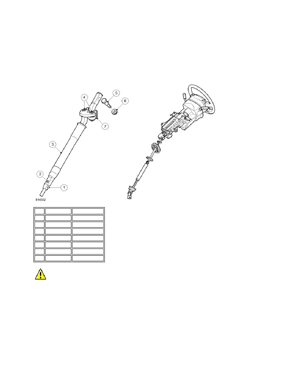
INTERMEDIATE SHAFT
The non-handed, intermediate shaft is attached at its upper end to the swivel yoke on the lower shaft of the steering
column assembly. The intermediate shaft comprises two main parts; the upper and lower axis which are joined together
with a shear joint.
The upper axis has a cut-out in the shaft which allows for the fitment of the cam bolt. Only when the shaft is located
correctly in the swivel yoke, can the cam bolt can be inserted. A self-locking nut is fitted to the cam bolt. The torque
applied as the nut is tightened, rotates the bolt, forcing the cam against the shaft, positioning it correctly in the swivel yoke
prior to the joint being clamped.
NOTE :
Item Part Number
Description
1
-
Alignment slot
2
-
Attachment hole
3
-
Seal sleeve
4
-
Load limiter pins
5
-
Cam bolt
6
-
Self-locking nut
7
Retention spring
CAUTION : Care should be taken when handling the intermediate shaft, to ensure that it is not subject to
impacts or that the retention spring is not displaced.