
LR3/Disco 3
The lower axis is fitted with a plastic moulded seal sleeve which provides a suitable surface for the location of the plastic
bearings within the two bulkhead seals. The bottom of the lower axis is machined to a double 'D' shape which tapers at
the end. One side of the taper has a slot which is used to align the intermediate shaft and the lower collapsible shaft to
ensure that the correct orientation of the steering wheel to steering gear is maintained. A hole is drilled through the double
'D' shape and provides for attachment of the intermediate shaft to the lower collapsible shaft.
The upper and lower axis are joined together via a load limiter. The load limiter is designed to disconnect the upper and
lower axis in the event of a collision, preventing an excessive load being applied to the steering column (causing intrusion
into the passenger compartment or an unstable airbag deployment).
The load limiter comprises two plates which are part of the upper and lower axis. The plates have a central 'guide' pin,
and two retention pins, which pass through bushes in the plates and are staked into position. The size of the staking
controls the load at which it shears, allowing the lower axis to separate from the upper axis. A wire 'retention' spring is
also fitted to the load limiter.
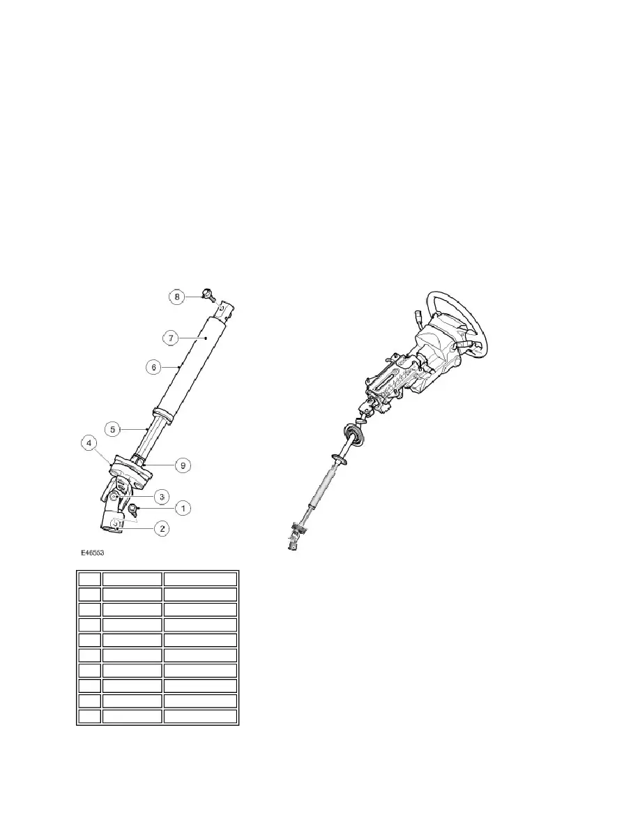
LOWER COLLAPSABLE SHAFT
The lower collapsible shaft is an handed component and the correct component must be fitted to ensure that the steering
phase angle is maintained. The shaft is attached at its upper end to the intermediate shaft and at its lower end to the
valve unit pinion on the steering gear. These attachment joints can only be fitted in one orientation to ensure that the
If the self-locking nut is removed for any reason, it is recommended that a new, correct nut is fitted to maintain the
optimum torque on the cam bolt.
Item Part Number
Description
1
-
Torx bolt
2
-
'U' yoke
3
-
Universal joint
4
-
Flexible coupling
5
-
Male shaft
6
-
Female shaft
7
-
Heat shield
8
-
Bolt
9
Plastic spacer