
LR3/Disco 3
correct alignment of the steering wheel to the steering gear. The shaft comprises two main parts; the female and male
shafts which are a telescopic fit on each other. The male shaft can slide up to 77 mm (3.03 in) within the female shaft in
the event of a collision, to minimize the effect of frontal intrusion. The sliding fit also allows for dynamic displacement
between the chassis and the body during severe off-road driving. A plastic spacer is fitted to the male shaft which is only
used as an assembly aid during vehicle production and serves no function once the shaft is assembled to the vehicle.
The female shaft is a triangular section tube which is formed to a double 'D' hole at its upper end which mates with the
intermediate shaft. An indentation pressed in the wall of the tube ensures the correct alignment between the intermediate
shaft and the lower collapsible shaft. A captive nut, clinched to one side of a through hole in the double 'D' section, allows
for the fitment of a patchlock bolt to secure the intermediate shaft. Clamped around the end of the female shaft is a dust
seal which prevents the ingress of dirt and moisture into the sliding joint, and a heat sleeve is also fitted to reflect radiant
heat from the exhaust.
The male shaft is a triangular section tube which is staked at its lower end into a flange. A cage and curved 'spring plates'
are fitted to its upper end, which slide in the female shaft. A pin is fitted into the side of the female tube, to secure the
male tube in the bore. The lower end of the male shaft is fitted with a flexible coupling to absorb vibration and steering
'kick back', transmitted from the steering gear. A 'Stabilising pin' is fitted through the coupling to prevent coupling
articulation (acting as a universal joint), while still allowing rotational flexing and plunge movement. The coupling is a
rubber moulding within which are nylon fibres wound around the attachment holes to transmit torque applied to the
steering. The coupling is attached to a drive flange (which is part of the male shaft), and to the 'U' yoke which in turn is
connected to the pinion yoke, by the universal joint assembly.
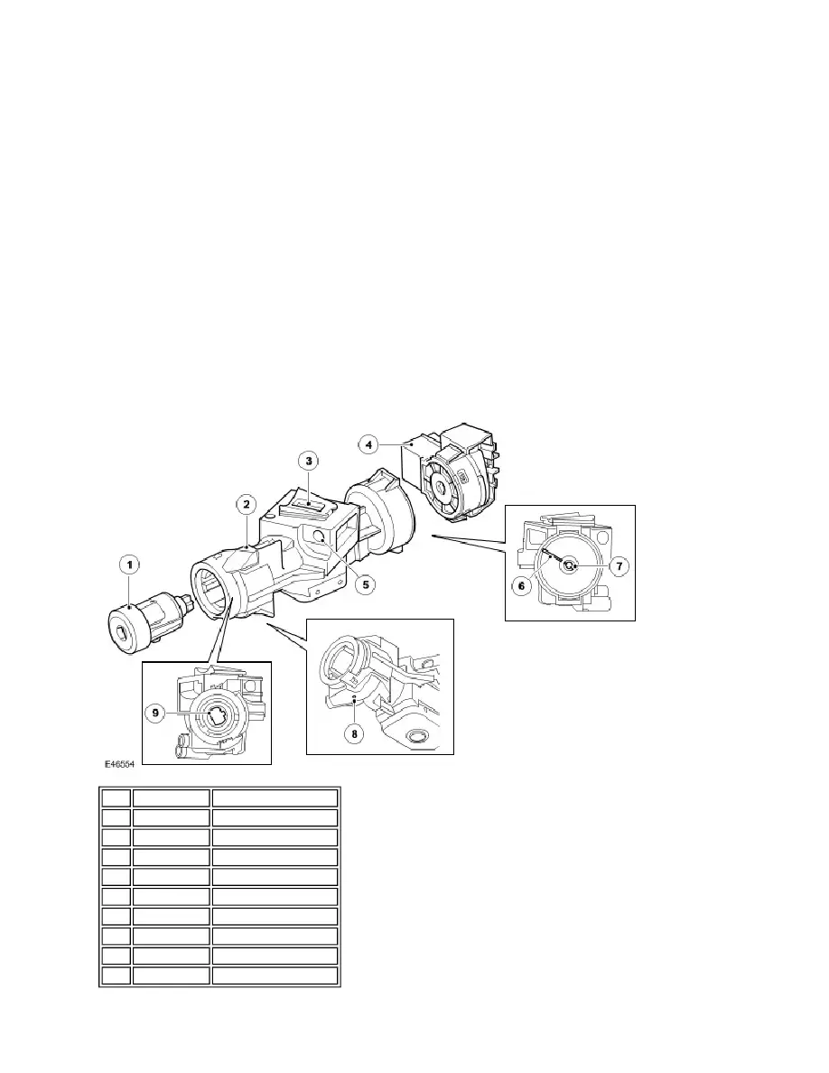
STEERING COLUMN LOCK
Item Part Number
Description
1
-
Ignition barrel
2
-
Column lock assembly
3
-
Lock bolt
4
-
Ignition switch
5
-
Attachment hole
6
-
Alignment mark
7
-
Switch drive
8
-
Barrel release hole
9
-
Barrel drive