
LR3/Disco 3
The turn signal indicator switch assembly is located in the left hand side of the case and is retained in the case with two
screws. The switch is connected to the main harness via a connector on the back of the switch. The switch controls the
following functions:
Left / right turn signal operation
High / low beam operation
Headlamp flash
Computer function selection (if fitted).
Turn Signal Indicators
The turn signal indicators are operated by pushing the switch up for right hand indicators and down for left hand
indicators. The switch has a detent position which locks the switch in the selected position until it is moved to the central
off position. The switch also has a 'lane change' function which allows the switch to be operated without moving through
the detent for use when changing lane on motorways or when overtaking. When released from the 'lane change' position,
the switch is automatically returned to the central off position. The left and right hand turn signal indicator switch positions
are connected on separate wires to the Central Junction Box (CJB) and the switch. When a switch position selection is
made, a circuit is completed from the CJB to ground, via the selected switch position. The CJB detects the completed
circuit and operates the selected turn signal indicator until the switch is moved to the central off position. The turn signal
indicators can be cancelled either manually by the driver or automatically when the steering wheel is rotated to the
straight ahead position.
High/Low Beam and Headlamp Flash
High beam is operated by pushing the switch forwards. The switch is latched in this position and the high beam is active
until the switch is manually pulled rearwards. The headlamp flash function is operated by pulling the switch rearwards.
The switch contacts complete a circuit and the headlamps are activated for as long as the switch is operated. The switch
is non-latching in this position and the headlamp flash is switched off when the switch is released and it returns to its off
position. The high beam and headlamp flash positions are connected on separate wires to the CJB and ground. When a
switch selection is made, a circuit is completed from the CJB to ground via the switch contacts.
Computer Function Button (if fitted)
This button is only fitted to vehicles with a high specification instrument cluster. The computer function button is located
on the end of the switch stalk. The button is a momentary switch and allows the driver to select the following information
in the instrument cluster message center:
Trip distance
Distance on fuel remaining in the fuel tank
Fuel tank remaining quantity
Average fuel consumption
Vehicle life fuel consumption
Average speed
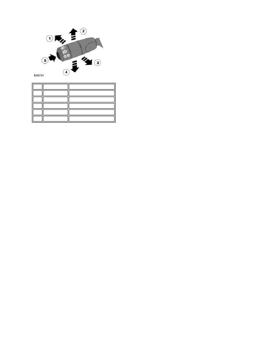
Item Part Number
Description
1
-
High beam
2
-
Right hand indicator
3
-
Headlamp flash
4
-
Left hand indicator
5
-
Computer function button