
LR3/Disco 3
Instantaneous fuel consumption.
The button is connected to the instrument cluster and ground. When the button is pressed the circuit is completed and the
instrument cluster displays the next trip computer information. Repeated presses of the button selects each display in the
message center in turn. For additional information, refer to
Information and Message Center
(413-08 Information and
Message Center)
Windshield Wiper Switch Assembly
The windshield wiper switch assembly is located on the right hand side of the case and is retained in the case with two
screws. The switch is connected to the main harness via a connector at the back of the switch. The switch controls the
following functions:
Windshield wiper intermittent, slow and fast speed
Windshield wiper flick wipe
Windshield wash/wipe
Rear wash/wipe
Intermittent delay selection.
For additional information, refer to
Wipers and Washers
(501-16 Wipers and Washers)
Windshield Wiper Switch Operation
The windshield wiper functions are operated by moving the switch up or down. Flick wipe is selected by pushing the
switch down. The switch is non-latching in this position and wiper operation is stopped when the switch is released and it
returns to the off position. The flick wipe switch contact is connected on a single wire to the CJB and ground. This is the
same connection to the CJB as the fast speed wipe. When the switch is operated the circuit is completed between the
CJB and ground. The CJB detects the completed circuit and operates the wipers for as long as the switch contact is
made.
Intermittent is selected by pushing the wiper switch up, to the detent position, the wipers operate at the delay period
selected on the rotary switch on the wiper stalk. The wipers remain in the intermittent mode until the wiper switch is
moved to the off or slow/fast speed positions. The intermittent switch contact is connected between the CJB and ground.
When the switch is moved to the intermittent position the circuit is completed. The CJB detects the completed circuit and
operates the wipers in the intermittent delay selected for as long as the switch contact is made.
The intermittent delay period is selected using a rotary control on the wiper switch stalk. The rotary control allows the
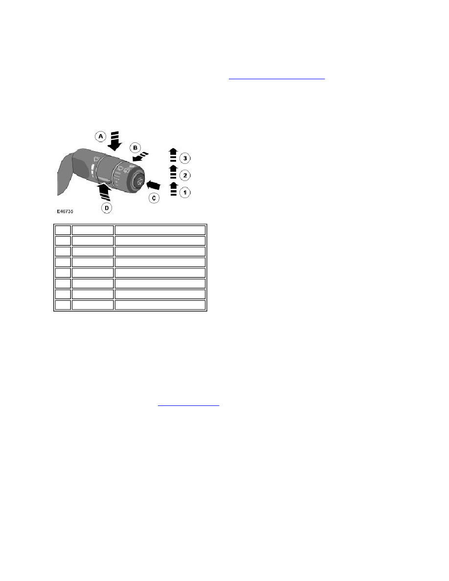
Item Part Number
Description
1
-
Intermittent position
2
-
Slow speed
3
-
Fast speed
A
-
Flick wipe
B
-
Rear wash/wipe
C
-
Wash wipe
D
-
Intermittent delay (6 positions)