
LR3/Disco 3
driver to select six delay periods to suit the prevailing weather conditions. The rotary control is connected on three wires
to the CJB and a single wire to ground. The six positions each use a different combination of the three wires. The CJB
detects, via the three wires, which selection has been made and operates the wipers with the appropriate delay.
Slow speed operation is selected by pushing the wiper switch up, to the second detent position. The wipers operate at
slow speed until the wiper switch is moved to the off, intermittent or fast speed positions. The slow speed switch contact is
connected between the CJB and ground. When the switch is moved to the slow speed position the circuit is completed.
The CJB detects the completed circuit and operates the wipers at slow speed for as long as the switch contact is made.
Fast speed operation is selected by pushing the wiper switch up, to the third detent position. The wipers operate at fast
speed until the wiper switch is moved to the off, intermittent or slow speed positions. The fast speed switch contact is
connected between the CJB and ground. When the switch is moved to the fast speed position the circuit is completed.
The CJB detects the completed circuit and operates the wipers at fast speed for as long as the switch contact is made.
Rear Wash/Wipe Switch Operation
The rear wash/wipe functions are operated by moving the switch rearwards. Rear wipe is selected by moving the wiper
switch rearwards to the first detent position. The rear wiper switch is connected between the CJB and ground. When the
switch is moved to the rear wiper position the circuit is completed. The CJB detects the completed circuit and operates the
rear wiper for as long as the switch contact is made.
The rear washer is selected by moving the wiper switch rearwards to the second, non-latching position. When the switch
is moved to this position a circuit is completed between the CJB and ground. The CJB detects the completed circuit and
operates the rear washer for as long as the switch contact is made.
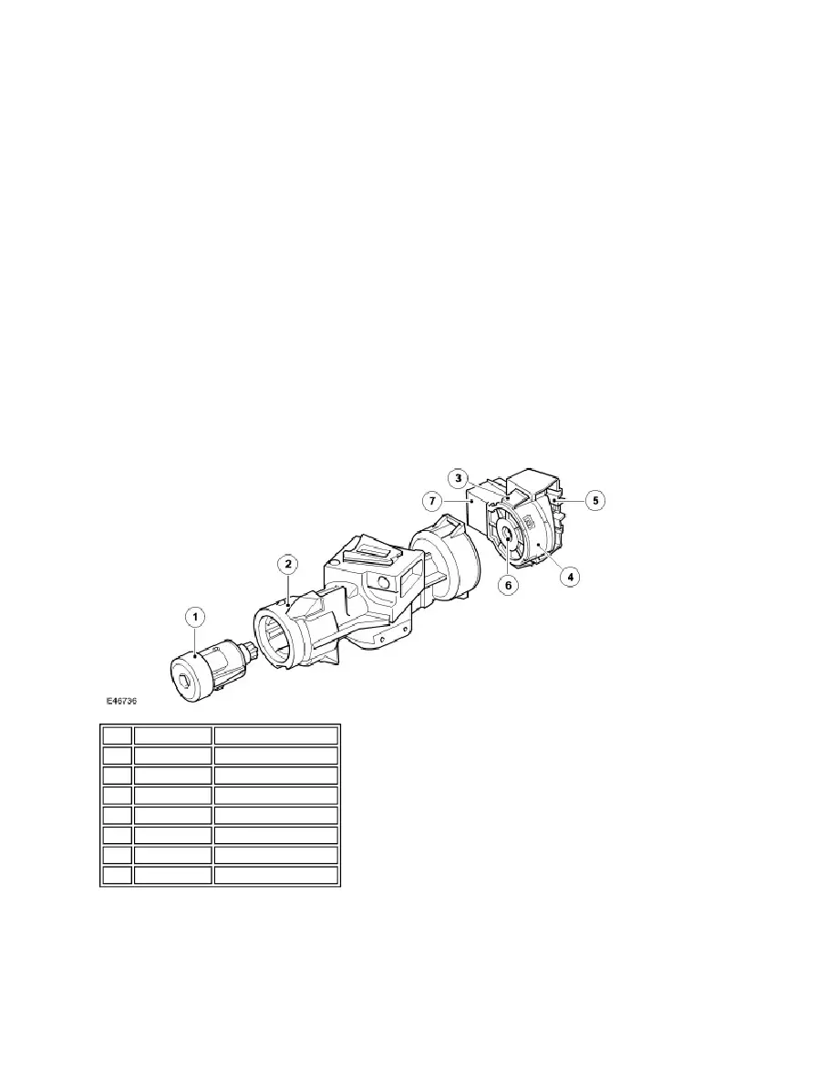
IGNITION SWITCH
The ignition switch is located in the left hand end of the steering column lock assembly. The switch is held in the column
lock casting with two locking tabs which engage in slots in the column lock casting.
The switch has a slot which provides for the location of the drive shaft which passes through the column lock. This shaft is
rotated by the driver when the ignition key is turned in the key barrel. This rotation turns a drum inside the ignition switch
which moves two electrical contacts to select the required ignition position. A spring loaded ball locates in a seat for each
of the three ignition switch positions, allowing the driver to feel when the required position is reached.
Item Part Number
Description
1
-
Key barrel
2
-
Column lock
3
-
Locking tab
4
-
Ignition switch
5
-
Harness connector
6
-
Drive shaft location
7
-
Key interlock solenoid