
LR3/Disco 3
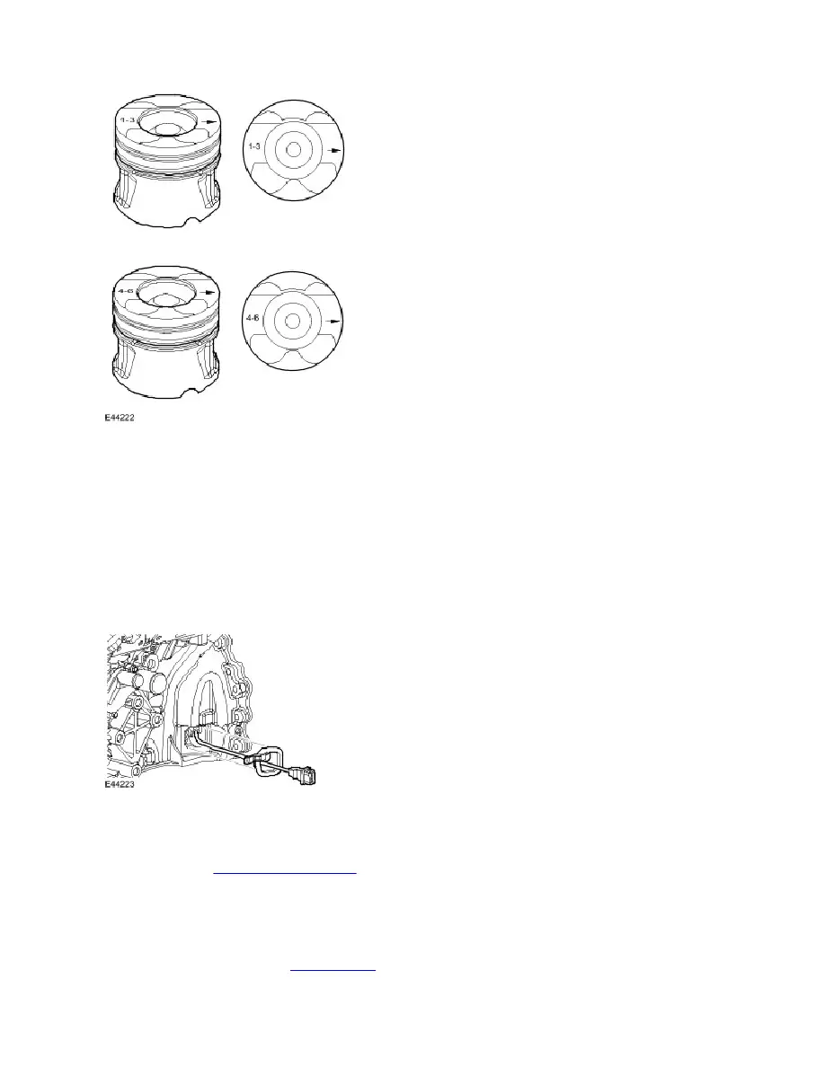
When installing pistons ensure the arrows on the piston crowns all point to the front of the engine and the pistons are
located in the correct cylinder banks, i.e. cylinders 1, 2, 3 or cylinders 4, 5, 6.
NOTE :
The piston top ring is a taper type and is fitted with the taper to the top of the piston. All rings marked 'top' are assembled
with 'top' uppermost. All rings must be spaced evenly around the piston before installing. The circumference gap of the
double bevelled oil control ring must be opposite the spiral control joint.
Crankshaft Position Sensor
The Crankshaft Position (CKP) sensor is located at the rear of the crankshaft, behind the flywheel in the LH side of the
rear oil seal retainer. The sensor provides an input of engine crankshaft speed and position. The sensor works on the
principle of the Hall effect and scans a trigger wheel (magnetic disc) on the crankshaft. An air gap of 0.4 to 1.5mm,
between the trigger wheel and the CKP sensor, is achieved by the positional mounting of the sensor. For additional
information, refer to
Electronic Engine Controls
(303-14C Electronic Engine Controls - 2.7L Diesel)
Starter Motor
The engine starter motor is installed at the rear RH side of the ladder frame, at the cylinder block to ladder frame split line.
For additional information, refer to
Starting System
(303-06C Starting System - 2.7L Diesel)
All pistons are common single grade/single part number for all engines.