
LR3/Disco 3
Engine cooling fan Speed
Engine speed and position sensor (crankshaft sensor)
Camshaft position sensor
Engine Oil Temperature
Inlet Air Temperature sensor (integrated into MAF)
Mass Air Flow sensor (MAF)
Knock sensors (2)
Cruise Control Switches (resistive ladders)
Oxygen sensors (4)
Vehicle Speed (via CAN)
EGR Differential Pressure
EGR MAP
Generator Monitor
Outputs
The ECM outputs to the following:
Throttle Actuator
Ignition coils (6)
Oxygen sensor heaters (4)
Fuel injectors (6)
EGR Valve
Inlet Manifold Tuning Valve (IMTV)
Purge Valve
Fuel pump relay
Starter Relay
Air conditioning condenser fan module (CAN)
EMS Main Relay
Viscous Fan Control
Generator Control
The ECM controls the engine fuelling by providing sequential fuel injection to all cylinders. Ignition is controlled by a direct
ignition system, provided by six plug top coils. The ECM is able to detect and correct for ignition knock on each cylinder
and adjust the ignition timing for each cylinder to achieve optimum performance.
The ECM uses a torque-based strategy to generate the torque required by the driver and other vehicle ECU's. The EMS
uses various sensors to determine the torque required from the engine. These include:
Mass Air Flow meter
Accelerator Pedal Position sensor
Engine temperatures
Oxygen sensors
The EMS processes these signals and decides how much torque to generate. Torque is then generated by using various
actuators to supply air, fuel and spark to the engine (electronic throttle, injectors, coils, etc.)The EMS also interfaces with
other vehicle ECU's, via CAN, to obtain additional information, these include
ABS control module
TCM
Transfer box control module
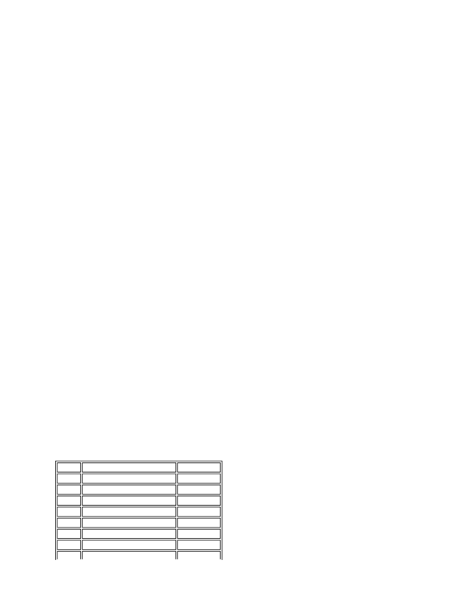
Pin No
Description
Input/Output
1
CAN
Input/Output
2
CAN
Input/Output
3
Generator monitor
Input
4
UHEGO Bank A ground
-
5
UHEGO Bank B ground
-
6
Crank sensor -
Input
7
Cam sensor ground
-