
LR3/Disco 3
Misfire Detection
Legislation requires that the ECM must be able to detect the presence of an engine misfire. It must be able to detect
misfires at two separate levels. The first level is a misfire that could lead to the vehicle emissions exceeding 1.5 times the
Federal Test Procedure (FTP) requirements for the engine. The second level is a misfire that may cause catalyst damage.
The ECM monitors the number of misfire occurrences within two engine speed ranges. If the ECM detects more than a
predetermined number of misfire occurrences within either of these two ranges, over two consecutive journeys, the ECM
will record a fault code and details of the engine speed, engine load and engine coolant temperature. In addition, the ECM
monitors the number of misfire occurrences that happen in a 'window' of 200 engine revolutions. The misfire occurrences
are assigned a weighting according to their likely impact on the catalysts. If the number of misfires exceeds a certain
value, the ECM stores catalyst-damaging fault codes, along with the engine speed, engine load and engine coolant
temperature.
The signal from the crankshaft position sensor indicates how fast the poles on the flywheel are passing the sensor tip. A
sine wave is generated each time a pole passes the sensor tip. The ECM can detect variations in flywheel speed by
monitoring the sine wave signal supplied by the crankshaft position sensor.
By assessing this signal, the ECM can detect the presence of an engine misfire. At this time, the ECM will assess the
amount of variation in the signal received from the crankshaft position sensor and assigns a roughness value to it. This
roughness value can be viewed within the real time monitoring feature, using T4. The ECM will evaluate the signal
against a number of factors and will decide whether to count the occurrence or ignore it. The ECM can assign a
roughness and misfire signal for each cylinder, (i.e. identify which cylinder is misfiring).
T4 Diagnostics
The ECM stores faults as Diagnostic Trouble Codes (DTC), referred to as 'P' codes. The 'P' codes are defined by OBD
legislation and, together with their associated environmental and freeze frame data, can be read using a third party scan
tool or T4. T4 can also read real time data from each sensor, the adaptive values currently being employed and the
current fuelling, ignition and idle settings.
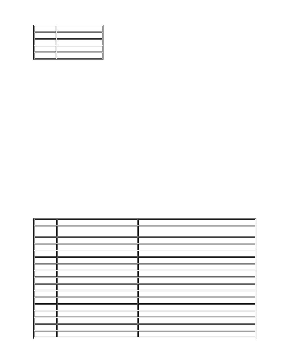
Adaptions Engine Speed, rev/min
1
1800 - 3000
2
3001 - 3800
3
3801 - 4600
4
4601 - 5400
P Code No
Component/ Signal
Fault Description
P0011
CMP/CKP/VVT
Bank A CMP/CKP Position error high , VVT retard position
high
P0012
CMP/CKP/VVT
Bank A CMP/CKP Position error low, VVT retard position low
P0021
CMP/CKP/VVT
Bank B CMP/CKP Position error, VVT retard position high
P0022
CMP/CKP/VVT
Bank B CMP/CKP Position error low , VVT retard position low
P0026
VVT
Bank A circuit malfunction range high/ low
P0028
VVT
Bank B circuit malfunction range high/ low
P0031
UHEGO
Bank A heater control circuit low
P0032
UHEGO
Bank A heater control circuit high
P0051
UHEGO
Bank B heater control circuit low
P0052
UHEGO
Bank B heater control circuit high
P0069
HAC
Sensor circuit/range performance
P0071
Ambient air temperature sensor
Range performance
P0072
Ambient air temperature sensor
Circuit low input
P0073
Ambient air temperature sensor
Circuit high input
P0075
VVT
Bank A open circuit
P0076
VVT
Bank A short to ground