
LR3/Disco 3
IMMOBILISATION
The immobilisation control module receives information from related systems on the vehicle and passes a coded signal to
the ECM to allow starting if all starting parameters have been met. The information is decoded by the ECM which will
allow the engine to run if the information is correct.
The information is on a rolling code system and both the immobilisation control module and the ECM will require
synchronisation if either component is renewed.
The ECM also protects the starter motor from inadvertent operation. The immobilisation control module receives an
engine speed signal from the ECM via the instrument cluster. When the engine speed exceeds a predetermined value,
the immobilisation control module prevents operation of the starter motor via an integral starter disable relay. For
additional information, refer to
Anti-Theft - Passive
(419-01B Anti-Theft - Passive)
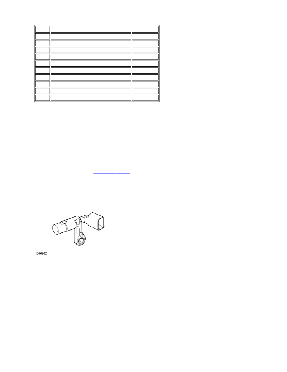
CAMSHAFT POSITION SENSOR (CMP)
The CMP is located on the front face of the left hand cylinder head. The sensor tip protrudes through the face to pick up
on the reluctor behind the camshaft pulley. The CMP is a Hall effect type sensor
The ECM uses the CMP sensor signal to determine if the piston in No. 1 cylinder is at injection TDC or exhaust TDC.
Once this has been established, the ECM can then operate the correct injector to inject fuel into the cylinder when the
piston is at injection TDC.
The CMP sensor is a Hall effect sensor which used by the ECM at engine start-up to synchronise the ECM with the CKP
sensor signal. The ECM does this by using the CMP sensor signal to identify number one cylinder to ensure the correct
injector timing. Once the ECM has established the injector timing, the CMP sensor signal is no longer used.
The CMP sensor receives a 5V supply from the ECM. Two further connections to the ECM provide ground and signal
output.
If a fault occurs, an error is registered in the ECM. Two types of failure can occur; camshaft signal frequency too high or
total failure of the camshaft signal. The error recorded by the ECM can also relate to a total failure of the crankshaft signal
or crankshaft signal dynamically implausible. Both components should be checked to determine the cause of the fault.
K2
VGT -
-
K3
Not used
Input
K4
Throttle valve actuator -
-
L1
Not used
-
L2
Injector 2 common
-
L3
Injector 0 common
-
L4
Injector 4 common
-
M1
Power ground
-
M2
Injector 2 command
Output
M3
Injector 0 command
Output
M4
Injector 4 command
Output