
LR3/Disco 3
If a fault occurs with the CMP sensor when the engine is running, the engine will continue to run but the ECM will
deactivate boost pressure control. Once the engine is switched off, the engine will crank but will not restart while the fault
is present.
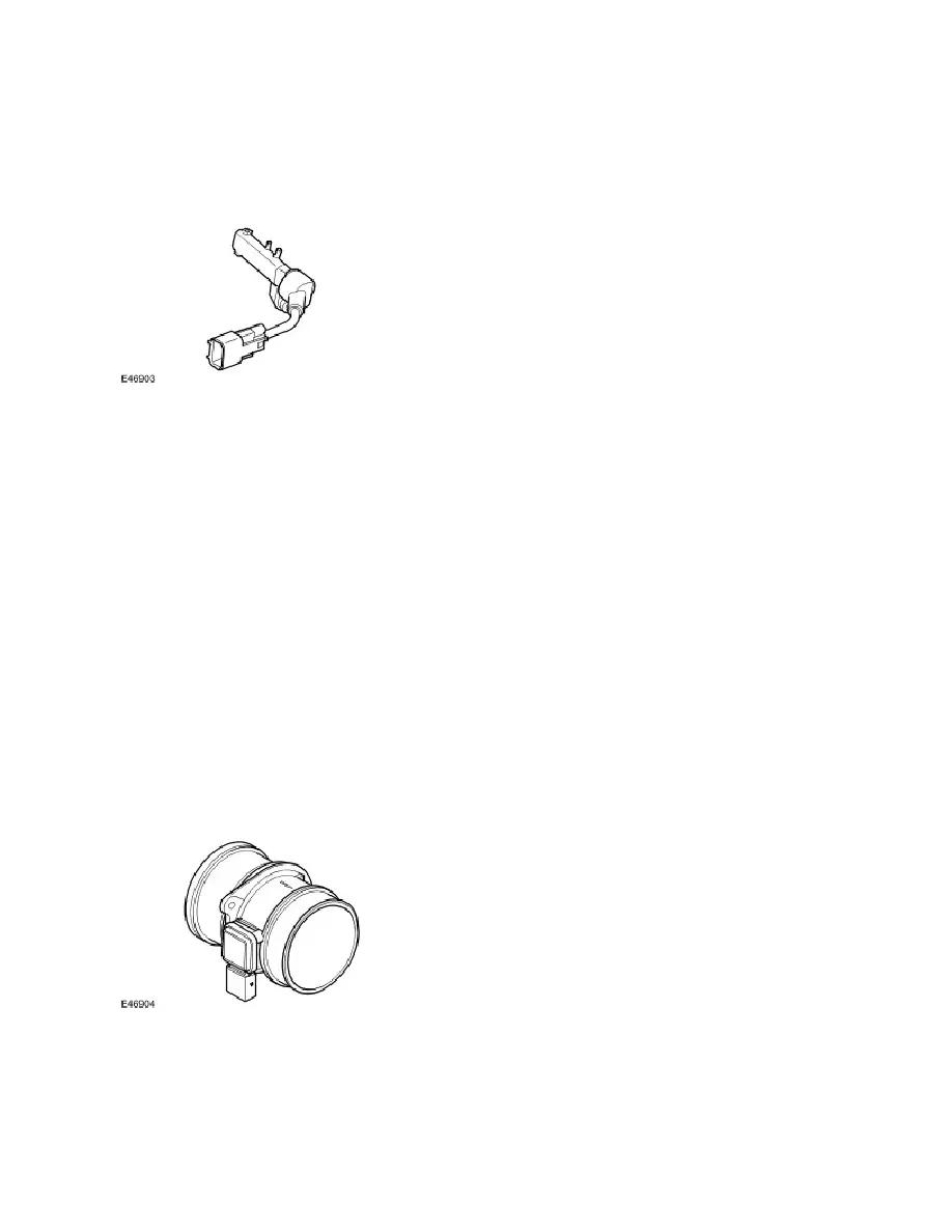
CRANKSHAFT POSITION SENSOR (CKP)
The CKP sensor is located at the rear of the engine block on the left hand side. The sensor tip is aligned with a magnetic
trigger which is attached to the crankshaft. The reluctor is a press fit on the end of the crankshaft. The trigger wheel must
be carefully aligned to the crankshaft to ensure correct timing. The sensor produces a square wave signal, the frequency
of which is proportional to engine speed.
The ECM monitors the CKP sensor signal and can detect engine over-speed. The ECM counteracts engine over-speed
by gradually fading out speed synchronised functions. The CKP is a Hall effect sensor. The sensor measures the
magnetic field variation induced by the magnetised trigger wheel.
The trigger wheel has two missing teeth representing 6º of crankshaft rotation. The two missing teeth provide a reference
point for the angular position of the crankshaft.
When the space with the two missing teeth pass the sensor tip, a gap in the signal is produced which the ECM uses to
determine the crankshaft position. The air gap between the sensor tip and the ring is important to ensure correct signals
are output to the ECM. The recommended air gap between the CKP and the trigger wheel is 0.4 mm- 1.5 mm.
The ECM uses the signal from the CKP sensor for the following functions:
Synchronisation.
Determine fuel injection timing.
Enable the fuel pump relay circuit (after the priming period).
Produce an engine speed signal which is broadcast on the CAN bus for use by other systems.
MASS AIR FLOW/INTAKE AIR TEMPERATURE (MAF/IAT) SENSOR
The MAF/IAT sensor is located on the inlet air duct directly after the air filter box. The sensor combines the two functions
of a MAF sensor and an IAT sensor in one unit. The sensor is housed in a plastic moulding which is connected between
the intake manifold and the air intake pipe.
The MAF sensor works on the hot film principle. Two sensing elements are contained within a film. One element is
maintained at ambient (air intake) temperature, e.g. 25°Celsius (77°F). The other element is heated to 200°Celsius (392°
F) above the ambient temperature, e.g. 225°Celsius (437°F). Intake air entering the engine passes through the MAF