
LR3/Disco 3
duty cycle which results in the injection quantity being limited.
FUEL VOLUME CONTROL VALVE
The fuel rail volume control valve is incorporated into the high pressure fuel pump. The VCV spills unwanted fuel back to
the tank (or LP system) or forwards it to the PCV. This avoids unused fuel being pressurised by the HP stage of the
pump, only to be spilt back to LP by the PCV wasting energy and heating the fuel.
INJECTORS
There are six electronic fuel injectors (one for each cylinder) located in a central position between the four valves of each
cylinder. The ECM divides the injectors into two banks of three with cylinders 1 to 3 being designated bank A and
cylinders 4 to 6 designated bank B, with injector numbers 1 and 4 at the front of the engine. Although the injectors are
numbered 1-6 the firing order determined by the ECM software is numbered 0-5.
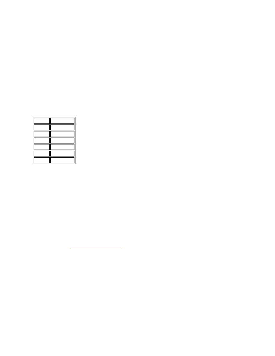
Injector/Cylinder Numbering
Each injector is supplied with pressurised fuel from the fuel rail and delivers finely atomised fuel directly into the
combustion chambers. Each injector is individually controlled by the ECM which operates each injector in the firing order
and controls the injector opening period via PWM signals. Each injector receives a 12V supply from the ECM and, using
programmed injection/timing maps and sensor signals, determines the precise pilot and main injector timing for each
cylinder. If battery voltage falls to between 6 and 9V, fuel injector operation is restricted, affecting emissions, engine
speed range and idle speed. In the event of a failure of a fuel injector, the following symptoms may be observed:
Engine misfire
Idle irregular
Reduced engine performance
Reduced fuel economy
Difficult starting
Increased smoke emissions.
The ECM monitors the wires for each injector for short circuit and open circuit, each injector and the transient current
within the ECM. If a defect is found, an error is registered in the ECM for the injector in question. For additional
information, refer to
Fuel Charging and Controls
(303-04C Fuel Charging and Controls - 2.7L Diesel)
EGR SYSTEM
The EGR system comprises:
EGR modulator x 2
EGR cooler x 2
Associated connecting pipes
EGR
Injector Cylinder No
0
1
1
4
2
2
3
5
4
3
5
6