
LR3/Disco 3
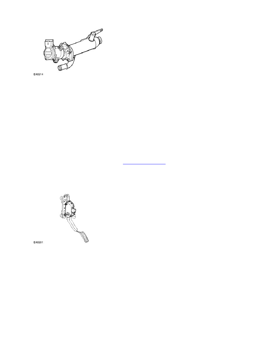
The EGR modulator and cooler are a combined unit.
The combined EGR modulator and cooler is located under each cylinder bank, between the exhaust manifold and the
cylinder head. The cooler side of the EGR is connected to the vehicle cooling system, via hoses. The inlet exhaust side is
connected directly into the exhaust manifolds on each side. The exhaust gas passes through the cooler and is expelled
via the actuator and a metal pipe into the throttle housing. The EGR modulator is a solenoid operated valve which is
controlled by the ECM. The ECM uses the EGR modulator to control the amount of exhaust gas being re-circulated in
order to reduce exhaust emissions and combustion noise. The EGR is enabled when the engine is at normal operating
temperature and under cruising conditions.
The EGR modulator receives a 12V supply from the ECM and is controlled using a PWM signal. The PWM duty signal of
the solenoid ground is varied to determine the precise amount of exhaust gas delivered to the cylinders.
The modulators are operated through their full range at each engine shut down, to clear any carbon deposits that may
have built up whilst the engine was running
In the event of a failure of the EGR modulator, the EGR function will become inoperative. The ECM can monitor the EGR
modulator solenoid for short circuits and store fault codes in the event of failure. The modulator can also be activated for
testing using T4. For additional information, refer to
Engine Emission Control
(303-08C Engine Emission Control - 2.7L
Diesel)
ACCELERATOR PEDAL POSITION SENSOR (APP)
The Accelerator Pedal Position Sensor (APP) is incorporated into the pedal assembly. The sensor is a twin track rotary
potentiometer type.
The APP sensor is located in plastic housing which is integral with the throttle pedal. The housing is injection moulded
and provides location for the APP sensor. The sensor is mounted externally on the housing and is secured with two Torx
screws. The external body of the sensor has a six pin connector which accepts a connector on the vehicle wiring harness.
The sensor has a spigot which protrudes into the housing and provides the pivot point for the pedal mechanism. The
spigot has a slot which allows for a pin, which is attached to the sensor potentiometers, to rotate through approximately
90°, which relates to pedal movement. The pedal is connected via a link to a drum, which engages with the sensor pin,
changing the linear movement of the pedal into rotary movement of the drum. The drum has two steel cables attached to
it. The cables are secured to two tension springs which are secured in the opposite end of the housing. The springs
provide 'feel' on the pedal movement and require an effort from the driver similar to that of a cable controlled throttle. A
detente mechanism is located at the forward end of the housing and is operated by a ball located on the drum. At near
maximum throttle pedal movement, the ball contacts the detente mechanism. A spring in the mechanism is compressed
and gives the driver the feeling of depressing a 'kickdown' switch when full pedal travel is achieved.