
LR3/Disco 3
ELECTRONIC THROTTLE
The electric throttle body is located in the inlet tract prior to where the inlet splits to divert air flow into the two separate air
intake manifolds. The electric throttle controls the volume of air allowed into the inlet manifold by means of a DC motor
which controls a flap in the body of the throttle. This is done in response to inputs from the engine management system.
Just after the throttle flap the tubes from the EGR valves/coolers are joined into the assembly.
TERRAIN RESPONSE ™
Terrain Response ™ system allows the driver to select a program which will provide the optimum settings for traction and
performance for prevailing terrain conditions.
As part of Terrain Response ™ there will be different throttle pedal progression maps associated with different Terrain
Response ™ modes. The two extremes are likely to be a sand map (quick build up of torque with pedal travel) and
grass/gravel/snow (very cautious build up of torque).
The TdV6 implementation of throttle progression is based on a fixed blend time. The torque will blend from that on one
map to that on the new map (for the same pedal position) over a fixed time. This means blending will always take the
same amount of time but when the torque change is small the torque increase over time will be small, whilst if the torque
change is greater then the torque increase over time will be steeper. The resulting acceleration of the vehicle will depend
on the torque difference between the two maps as well as on the gear and range selected. The worst case blending that
could ever occur has been calibrated to match the blend rate for petrol derivatives as closely as possible, so as to give a
transparent behaviour to customers. For additional information, refer to
Ride and Handling Optimization
(204-06 Ride
and Handling Optimization)
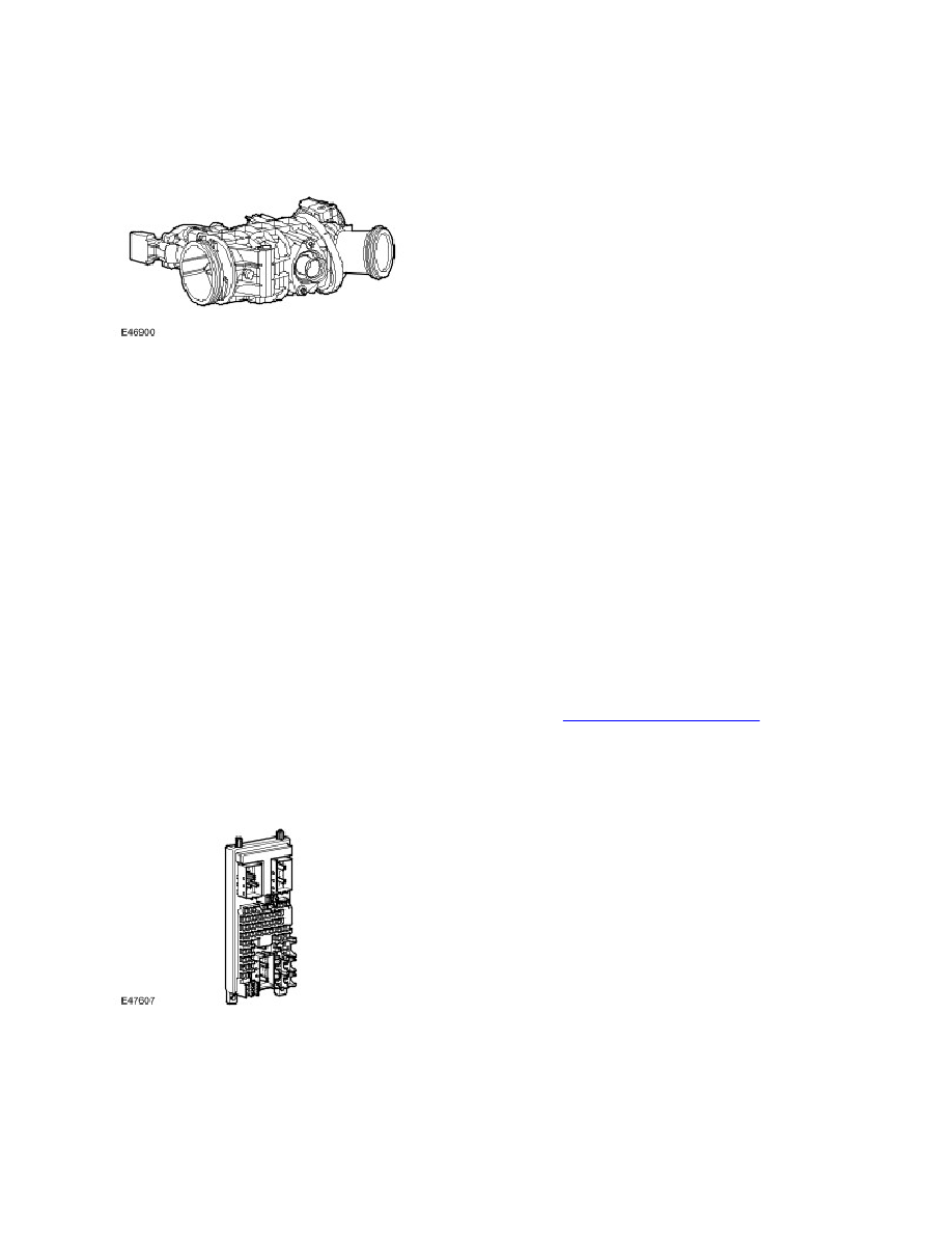
CENTRAL JUNCTION BOX
The CJB initiates the power up and power down routines within the ECM. When the ignition is turned on 12V is applied to
the Ignition Sense input. The ECM then starts its power up routines and turns on the ECM main relay; the main power to
the ECM and it's associated system components. When the ignition is turned OFF the ECM will maintain its powered up
state for up to 20 seconds while it initiates its power down routine and on completion will turn off the ECM main relay.
GENERATOR