
LR3/Disco 3
TCM and displayed to the driver in one of two displays in the instrument cluster. For additional information, refer to
Instrument Cluster
(413-01 )
Malfunction Indicator Lamp (MIL)
The MIL is located in the tachometer in the instrument cluster. Transmission related faults which may affect the vehicle
emissions output will illuminate the MIL.
The MIL is illuminated by the ECM on receipt of a relevant fault message from the TCM on the high speed CAN. The
nature of the fault can be diagnosed using T4 which reads the fault codes stored in the TCM memory.
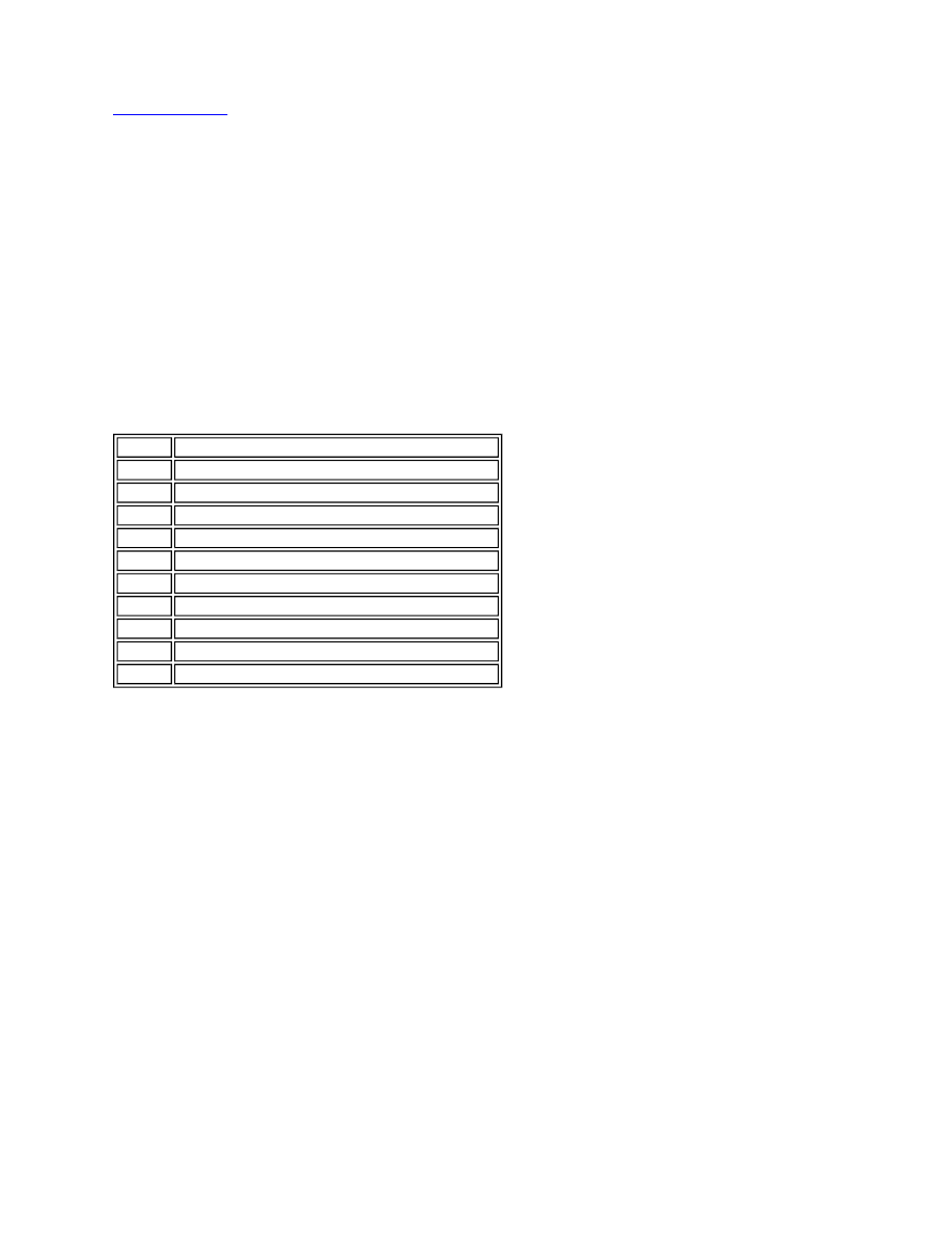
Transmission Status Display
The transmission status display is located in a Liquid Crystal Display (LCD) within the speedometer housing. The LCD
shows the selector lever position and the selected transmission mode. When the selector lever is in the manual
CommandShift™ position, the selector lever position display will show the selected gear ratio.
The following table shows the displays and their descriptions.
Message Centre Display
The message centre is located in the lower centre of the instrument cluster. The message centre is a LCD to relay vehicle
status and operating information to the driver. The message centre can display messages relating to a number of the
vehicle systems. The following list shows the possible transmission related messages:
TRANSMISSION FAULT LIMITED GEARS AVAILABLE
TRANSMISSION FAULT AND OVERHEAT
TRANSMISSION FAULT
TRANSMISSION OVERHEAT
TRANSMISSION CONTROL MODULE (TCM)
The TCM is an integral part of the Mechatronic valve block which is located at the bottom of the transmission, behind the
fluid pan. The TCM is the main controlling component of the transmission.
The TCM processes signals from the transmission speed and temperature sensors, engine control module and other
vehicle systems. From the received signal inputs and pre-programmed data, the module calculates the correct gear,
torque converter clutch setting and optimum pressure settings for gear shift and lock-up clutch control.
The TCM outputs signals to control the shift control solenoid valve and the Electronic Pressure Regulator Solenoids
(EPRS) to control the hydraulic operation of the transmission.
The ECM supplies the engine management data on the high speed CAN bus system. The TCM requires engine data to
efficiently control the transmission operation, for example; flywheel torque, engine speed, accelerator pedal angle, engine
Symbol
Description
P
Park selected
R
Reverse selected
N
Neutral selected
D
Drive selected
1
1st gear selected (Manual CommandShift™ mode)
2
2nd gear selected (Manual CommandShift™ mode)
3
3rd gear selected (Manual CommandShift™ mode)
4
4th gear selected (Manual CommandShift™ mode)
5
5th gear selected (Manual CommandShift™ mode)
6
6th gear selected (Manual CommandShift™ mode)