
LR3/Disco 3
temperature etc.
The steering angle sensor and the ABS module also supply data to the TCM on the high speed CAN bus sytem. The
TCM uses data from these systems to suspend gear changes when the vehicle is cornering and/or the ABS module is
controlling braking or traction control.
The selector lever is connected to the automatic transmission and the position switch in the transmission by a Bowden
cable. Movement of the selector lever moves the position switch via the Bowden cable and the switch position informs the
TCM of the selected position. The sport/manual +/- CommandShift switch passes manual/sport selections to the TCM. An
additional switch provides a selector lever in park position signal. Once the selector lever position is confirmed, the TCM
outputs appropriate information which is received by the instrument cluster to display the gear selection information in the
message centre.
The Mechatronic valve block also contains the speed and temperature sensors. These are integral with the Mechatronic
valve block and cannot be serviced individually. The speed sensors measure the transmission input and output speeds
and pass signals to the TCM. The fluid temperature sensor is also located in the valve block and measures the fluid
temperature of the transmission fluid in the fluid pan.
The TCM is connected to the starter relay coil. When the selector lever is in PARK or NEUTRAL, the module provides a
ground for the coil allowing the starter relay to be energised and allow starter motor operation. If the selector lever is in
any other position, the module will not provide the ground preventing starter motor operation.
Inputs and Outputs
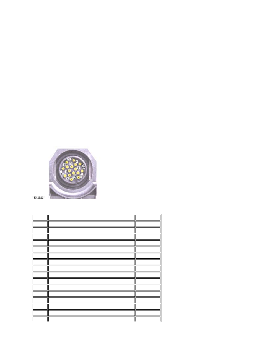
Connector C0193
The following table shows the connector pin details for the connector on the transmission.
Pin No.
Description
Input/Output
1
Manual/sport shift programme selection
Input
2
CAN low
Input/Output
3
Diagnostic ISO9141 K Line bus
Input/Output
4
CommandShift™ - (downshift)
Input
5
CommandShift™ + (upshift)
Input
6
CAN high
Input/Output
7
Shiftlock power supply
Output
8
Not used
-
9
Ignition position II supply 12V
Input
10
Park/Neutral signal (starter inhibit)
Input
11
Shiftlock ground
Output
12
Selector lever in park position confirmation signal
Input
13
Ground 1
-
14
Permanent power supply 12V
Input
15
Not used
-