
LR3/Disco 3
attached to the front end of the transmission via 3 bolts. These bolts are asymmetrically positioned to ensure correct
angular location of the slave cylinder, which is also spigot-mounted for positional fit. In its free condition the slave cylinder
is fully extended, but it positions itself automatically as the clutch housing is fitted to the engine. The assembly requires no
setting or adjustment.
CLUTCH COVER ASSEMBLY
The clutch cover assembly is known as a self-adjusting clutch with a nominal diameter of 260mm.
Self Adjusting Clutch
The self-adjusting clutch contains a mechanism, which improves operation and driver comfort by enabling a more
consistent pedal load as the friction faces wear, unlike conventional types of clutch which exhibit increasing pedal load
with wear.
With a conventional clutch, facing wear causes the angle of the actuating diaphragm spring to change as the pressure
plate moves axially towards the engine, requiring a greater force to operate the clutch (diaphragm actuating force varies
with diaphragm angle). The self-adjusting clutch reduces this problem by allowing the diaphragm spring to follow the axial
movement of the pressure plate thus maintaining the diaphragm spring at the same angle throughout the life of the clutch.
As well as maintaining a more consistent pedal load, the clamp force on the pressure plate also remains constant with
wear.
The diaphragm spring is not fixed at its rotation point like the conventional system but pivots between a sensor spring and
an adjuster ring. The sensor spring provides a counter force, which is just sufficient to retain the diaphragm spring axially
against the cover via the adjuster ring and during normal actuation of the clutch. As the linings wear, the tendency of the
diaphragm angle to change causes an increase in the actuation force required to operate the clutch. When this increased
effort exceeds the counter force of the sensor spring, the diaphragm spring moves axially towards the pressure plate until
the original angle is restored. At this point the actuation force required drops to the level of the opposing sensor spring
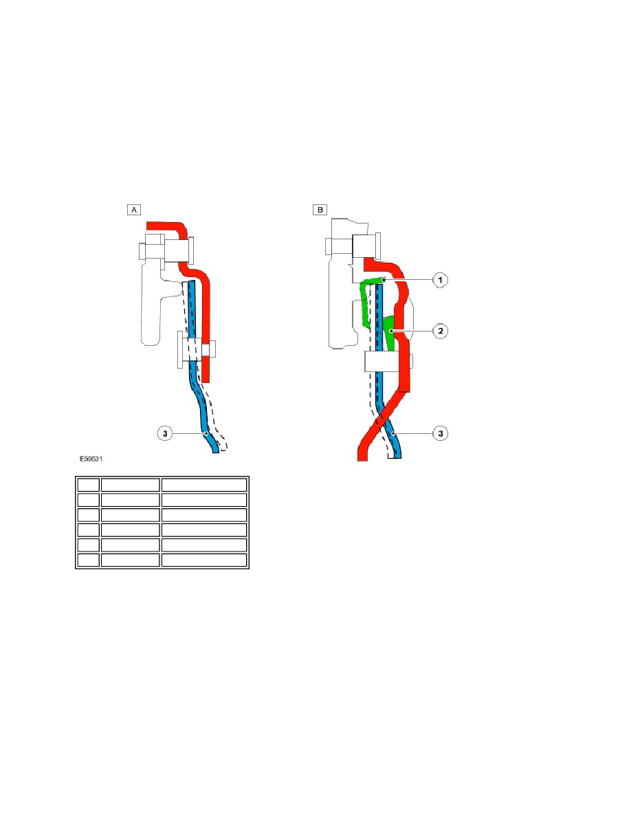
Item Part Number
Description
A
-
Conventional clutch
B
-
Self adjusting clutch
1
-
Sensor spring
2
-
Adjuster ring
3
-
Diaphragm spring